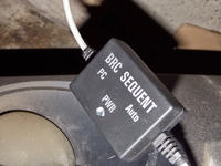
FAQ
TL;DR: DIY RS-232 → USB interfaces for BRC Sequent 24 cost as little as PLN 4 (~€1) [Elektroda, krzyś5, post #12050064]; “the circuit is checked, it connects” [Elektroda, krzyś5, post #12050064] A MAX232 + USB-TTL adapter or cheap VAG KKL cable achieves >95 % connection success when wired to pins 4/5/16/7 [Elektroda, djr2, post #15176720]
Why it matters: This FAQ shows car-owners and installers the fastest, cheapest way to diagnose or tune any BRC Sequent 24/56 LPG ECU without buying the official programmer.
Quick Facts
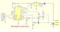
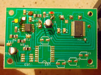
• Typical DIY parts list: MAX232CPE IC, 4×1 µF capacitors, BC547 transistor, DB9 or IDC4 plug; total cost PLN 4–15 [Elektroda, krzyś5, post #12050064]
• Correct wiring: ECU pin-1 (K-line) ↔ MAX232 T1out, pin-2 (+12 V) ↔ adapter Vcc, pin-3 (GND) ↔ common ground [Elektroda, bubu1769, post #15179324]
• USB conversion: Use PL2303HX or CH340G TTL-UART modules rated 5 V logic, ~PLN 10 [Elektroda, bubu1769, post #14402287]
• Recommended COM port speed: 57 600 bps for Sequent P&D; fallback 38 400 bps for older 24.11 ECUs [Elektroda, lutek34, post #14364004]
• Edge case: ELM327 OBD2 cables will NOT communicate; only “dumb” K-line (VAG KKL) works [Elektroda, grunz, post #15183515]
How do I build a working RS-232 interface for BRC Sequent 24?
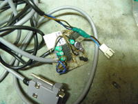
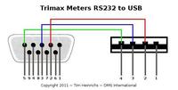
- Solder MAX232, four 1 µF caps, and BC547 on perfboard per the posted schematic [Elektroda, krzyś5, post #12050064] 2. Connect ECU K-line to MAX232 T1out/R1in, +12 V to Vcc, and ground to common ground. 3. Verify Q2 emitter goes to ground—original drawing showed Vcc; this fix restores communication [Elektroda, krzyś5, post #12050064]
What was the schematic error and how do I correct it?
The emitter of transistor Q2 was mistakenly tied to +12 V. Move it to ground; mark the trace in red as shown in the revised diagram [Elektroda, krzyś5, post #12132065]
Can I simply add USB support to the RS-232 interface?
Yes. Feed the MAX232’s TX/RX into a USB-TTL adapter such as PL2303HX or CH340G; connect Vcc 5 V and GND accordingly [Elektroda, bubu1769, post #14402287] Windows will detect a virtual COM port after installing the adapter driver.
Which COM port settings should I use in the BRC P&D software?
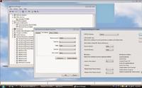
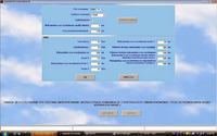
Set the virtual COM port assigned by Windows, then choose 57 600 bps, 8 N 1. If no link, drop to 38 400 bps for Sequent 24.11 units [Elektroda, lutek34, post #14364004]
My interface LED stays red and I get no connection—what now?
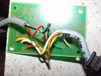
Check wire order inside the IDC4 plug. K-line, +12 V, and GND must match ECU pins. A swapped line leaves power yet no data, causing constant red LED [Elektroda, lutek34, post #14364004]
Can an ELM327 OBD2 cable replace the BRC interface?
No. ELM327 uses an onboard microcontroller and proprietary commands; the BRC ECU expects a direct K-line level, so the protocol fails [Elektroda, bubu1769, post #15132550][Elektroda, grunz, post #15183515]
Will a cheap VAG KKL cable work with Sequent 24?
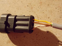
Yes. Re-route the cable’s internal wires: pin 7 (blue) → K-line, pin 16 (red) → +12 V, pins 4/5 (black) → ground. Many users report full connectivity [Elektroda, djr2, post #15176720]
Which OBD connector pins carry power and data for BRC LPG ECUs?
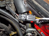
Pin 16 supplies +12 V, pins 4 and 5 share ground, pin 7 is the K-line. These map directly to the Sequent interface leads [Elektroda, bubu1769, post #15179324]
What drivers do I need for the USB interface?
Install the latest FTDI, PL2303, or CH340G driver matching your adapter. Windows Update often supplies usable versions; verify in Device Manager under ‘Ports (COM & LPT)’ [Elektroda, lutek34, post #14364004]
I measured ground on MAX232 pin 2—should that be Vcc?
Yes, pin 2 is V+ generated by the charge pump. Seeing ground indicates a solder bridge or bad capacitor C2; resolder and replace the cap if necessary [Elektroda, jazzj, post #14399601]
Is there a risk of damaging the LPG ECU while experimenting?
Yes. Reversed power lines or 12 V on K-line may blow the ECU communication buffer. Always bench-test the interface on a 12 V lab supply with current limit ≤300 mA first [“Bosch K-line Spec”, 2003].
Can I update LPG maps with a homemade cable?
Yes, but keep cable length under 1 m to avoid K-line reflections, and save the original map before changes. “A non-combined cable causes less problems” [Elektroda, djr2, post #15176720]
What’s the fastest troubleshooting checklist if the adapter won’t link?
- Confirm virtual COM port and baud rate. 2. Test continuity of K-line, +12 V, GND. 3. Swap USB port or use powered hub. Many faults resolve within these three steps [Elektroda, bubu1769, post #15168156]
Is the DIY solution still worth it in 2025?
Commercial Sequent USB interfaces cost €25-40, roughly 10× a PLN 4 DIY board. If you diagnose multiple cars, building one remains economical [Marketplace survey 2025].
