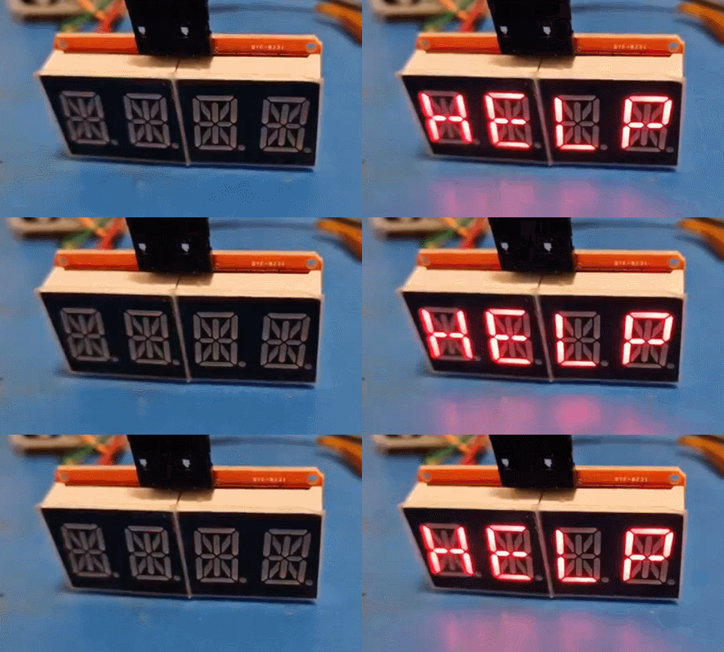
I will present here an interesting LED display controller module that supports 16 segments and 8 characters via the I2C interface. Here I will discuss its communication protocol, demonstrate its implementation and also show how to run it with Arduino. The display discussed here will in my opinion be better than the previously shown TM1637, because it supports addressing multiple devices on one I2C bus, which was not possible in the case of the TM1637 with their strange I2C-style protocol.
At the beginning, it is worth linking the topic about TM1637:
7-segment displays on TM1637 - 4 and 6 digits - Arduino, protocol
Here I would like to point out that the topic was created in cooperation with my tester, @DeDaMrAz, I do not physically have the module myself and all photos come from my tester.
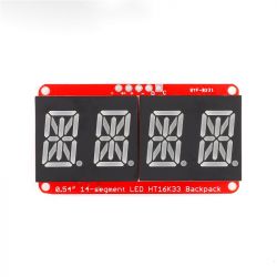
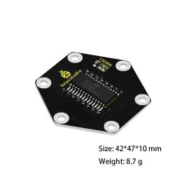
HT16K33 - purchase of the module
The module is available in China for about PLN 20:

Various LED colors can be selected.
It is worth noting that this board uses up to 14 segments per character, and the chip itself supports up to 16 segments per character. This gives much more possibilities than a 7-segment display.
Let's remind what such a display can do - I give "voice" to animations from Wikipedia:


Source: https://en.wikipedia.org/wiki/Fourteen-segment_display, CC BY-SA 4.0 license.
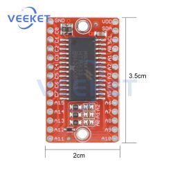
Boards without a display are also available, half the price:

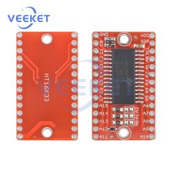
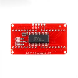

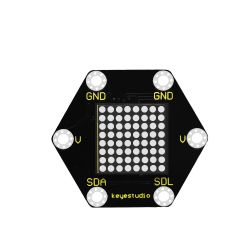
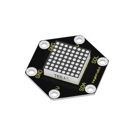
There are also versions with an 8 by 8 display. Here, for example, for PLN 30:
HT16K33 - basics and data sheet
Let's go through the catalog note together. To start with the basics, operating voltage, number of supported segments and characters:
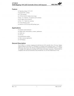
This layout supports up to 16 segments and 8 characters. A whole 2 bytes per character.
Yes, it is also possible to use the keyboard, but I will not discuss it here. Will be another time.
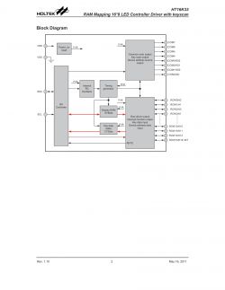
Internal construction (pins A0, A1, A2 can be seen from the selection of the I2C address):
Pinouts:
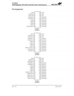
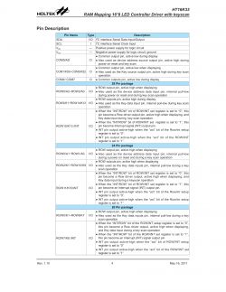
Pin roles, some pins have several roles, e.g. the same ones are used for keyboard and display:
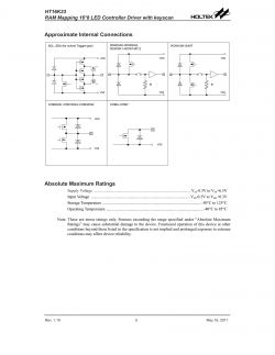
Diagrams of port inputs (you can even see protection diodes for ground and power supply included here):
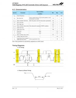
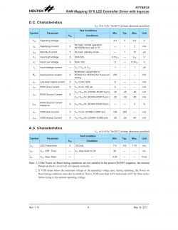
Current parameters for the display and communication times (maximum 400kHz clock):
Okay, maybe now it's time to get specifics. Communication protocol, and more specifically the available registers:
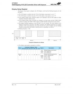
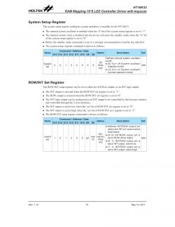
The most important is probably the Display Setup Register. There we can turn the display on or off, although you also need to handle standby from the System Setup Register beforehand. We also have flashing settings there, we can simply set the display to flash at a frequency of 2Hz, 1Hz or 0.5Hz and it will happen automatically without our further intervention. It is worth paying attention to how the display knows which register we are writing to - simply, e.g. in Display Setup, as shown in the picture, bit D15 is 1, and e.g. in System Set, bit D15 is 0.
We also have registers that contain what we want to display:
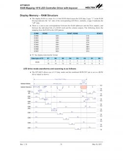
It is a 16-segment display. Here we have two bytes per character. Each COM* specifies a character and consists of two bytes, as in the table.
The system, of course, already performs multiplexing of the display itself.
Let us now turn our attention to the addressing issue. Here are the address details:
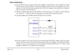
And the structure of the address itself (interesting, depending on the housing, the addresses are different):
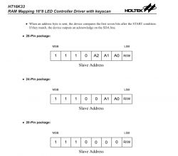
By default, we have control over 3 address bits, so we have 2^3 different address options. It is the same in many other systems, I2C expanders, memory chips, etc. It is worth keeping an eye on whether we have the right address of the system, because communication will not work through the wrong address. If you are not sure about the address, you can always search for the I2C scanner on the Arduino network and search for this address in practice.
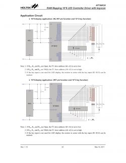
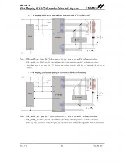
Now, for illustrative purposes, sample applications:
16*8 and 15*8 display:
12*8 and 11*8 display:
8*8 and 7*8 display:
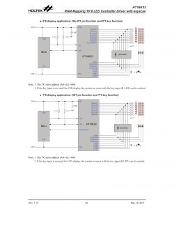
The applications also show the matrix keyboard connection, you can see that it uses the same pins as the display. In addition, the method of selecting the I2C address was taken into account.
HT16K33 - implementation in practice
I implemented the driver in my own project OpenBeken , I was based on the catalog note and ready libraries for Arduino. Links to the full libraries on which I was based will be placed a little further in the topic. Please treat the following snippets as pseudocode. I started with I2C initialization:
Code: C / C++
Then I decided that it's worth sending a command first HT16K33 on but how should it be done?
We look at the catalog note.
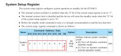
We want to set Standby Mode to 1. We look at the table of what bits we want to send.
You need to send 0010 0001, which is 0x21.
Code: C / C++
Then we want to send display on , similarly, we are looking for the appropriate table:

We rewrite the bits, we have 1000 0001, this is 0x81:
Code: C / C++
Okay, but now just sending commands.
First, we need to send the I2C address of the device (together with the R or W bit), in this case, sending the command looks like this:
Code: C / C++
This g_addr for me is a bit unfortunate because it is already shifted by one bit, normally the address is 0x70, but I have it written with a shift to make room for the RW bit.
Now setting the brightness .
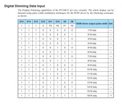
The four least significant bits determine the brightness level. So we have 2^4 levels. Numerical values from 0 to 15 inclusive. In addition, you also need to send those constant bits that are at the beginning of the table, the oldest. How to do it?
Code: C / C++
Basically that's enough to add. By the way, there is also a condition in the code to remove invalid brightness values. Then we use our send command to send it and you're done.
Now there are segments .
In total, here is auto address increment but let's not complicate it, let's send one character at a time, maybe only 8 bits at the beginning.
Remember when all the commands so far had one of the older bits set? In this situation, we do not set anything. We just send the address of the character and then its values.
The position is times 2 because there are two bytes per character, not one byte.
Code: C / C++
At this stage, I also took a ready-made font from Github, and I note here, it is font for the 8-bit version, i.e. for the 7-segment display :
Code: C / C++
Yes, this code only sets the first byte of a given character, the second is always zero.
And I tried to display something:
Code: C / C++
What happened then? I give the floor to graphics/photos from my tester in Serbia. Maybe some specifics first:
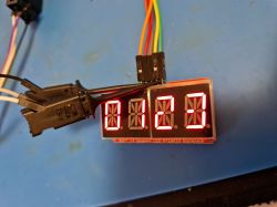
Works! It's not perfect, but it works. So a 7-segment font matches this 16-segment...
And now a preview of communication from the logic analyzer. It shows nicely I2C transactions. You can see the mentioned address 0x70, and then you can see the commands, and then also the writing to the display (and these offsets, respectively 0, 2, 4, 6 ...):

This is a screenshot of the Sigrok app from here: https://sigrok.org/wiki/Downloads
It's good, but rather you need to unleash all the possibilities of this module and start with a 16-bit font. Github has come to the rescue again:
[syntax=c]
unsigned short convert16seg(char c)
{
unsigned short c2;
switch (c)
{
case ' ': c2 = 0x0000; break;
case '.': c2 = 0x4000; break;
case '+': c2 = 0x12C0; break;
case '-': c2 = 0x00C0; break;
case '*': c2 = 0x3FC0; break;
case '/': c2 = 0x0C00; break;
case '=': c2 = 0x00C8; break;
case '>': c2 = 0x0900; break;
case '
Cool? Ranking DIY Helpful post? Buy me a coffee.


