logo elektroda
logo elektroda
X
logo elektroda

SIMAT-25 Control object simulator for PLCs

Andrzej_Tomaszewski 2553 17
ADVERTISEMENT
Treść została przetłumaczona polish » english Zobacz oryginalną wersję tematu
  • SIMAT-25 signal simulator on a wooden table with displays and switches. .

    Welcome.

    Some time ago I started my adventure with PLC programming. To start with, I found that Siemens LOGO! was sufficient. Creating a program in FBD language is quite transparent but, as you know, the created program must somehow affect reality. It is a good idea to test the written programme on a workbench in order to identify and repair potential errors before the whole assembly is assembled in the final location. This involves simulating certain states to the controller at its inputs and visualising states at its outputs to determine if the application is functioning as expected. I found that combining with switches, lights, potentiometers, etc. was not very convenient. I found signal simulators dedicated to LOGO! on the web, but for various reasons I refrained from buying one. I decided that I would design and make my own simulator. It was to be a compact design providing all the basic signals for the PLC under test. And so the device I called SIMAT-25 was created, and many factors determined this name.

    The complete device is shown in the photograph below.
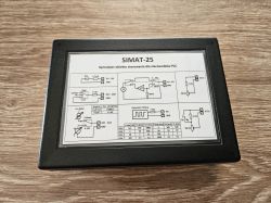
    SIMAT-25 simulator casing with diagram on top .

    The case is a Z33 model from a well-known company in the industry. Dimensions: height 46.0 mm, width 140.0 mm, length 190.0 mm. On the lid there is a plate showing in simplified form the idea of the construction of the individual signal tracks. For those in the trade, this information contains all the necessary data. The lid protects the panel components from mechanical damage. When the lid is removed, the panel is visible.
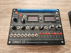
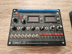
    SIMAT-25 signal simulator for PLC environment. .

    On the side of the case there is a DC 2.5/5.5 socket for connecting a 24VDC power supply ("plus" inside).
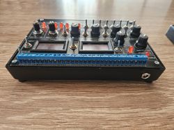
    SIMAT-25 controller with knobs and switches on a wooden table. .

    The simulator is designed for PLCs supplied with 24V DC. The power supply is connected to the ARK connectors with the description +24V DC and GND. The GND terminal is common to the power supply and the simulated signals. In this way, the power supply for the simulator can be taken from the system in which the PLC under test is running. It is also convenient to use an additional 24VDC power supply and connect it to the DC 2.5/5.5 connector on the side of the housing. In this way, the controller under test can be powered by wires plugged into the ARK +24VDC and GND connectors and in this way it is the simulator that powers the controller under test. This way of power supply suits me so far.
    The main electronics board of the simulator is also the front panel. All electronic components are smd type and are located on the underside of the board. The main board itself has protection against reverse connection of the supply voltage, while the corresponding pins of the DC supply connector and the ARK +24VDC and GND terminals are directly connected to each other.
    Correct connection of the power supply is indicated by the illumination of the red LED with the description PWR.
    Sets of potentiometers, switches, LEDs, displays are given names identifying the supported function/signal. The corresponding names are also found on the ARK screw terminals, so it is immediately clear which connector is the signal of interest.

    Signals and their characteristics:

    DO1-DO8: three-state digital output: logic 1 "High" state (short-circuits to plus supply), logic 0 "Low" state (short-circuits to GND) and high impedance state (output "hangs in the air"). There is a 1k/1W resistor in series at the output of each DO signal. This protects both the simulator and the PLC from connection errors (short circuit). A value of 1k is sufficient for a correct reading via the DI input of the PLC.

    DI1-DI8: digital input. LEDs with series resistors. The current drawn by one input for 24V DC is approximately 4.5 mA.

    AO1-AO4: analogue outputs 0-10V and 0-20mA selectable by switches. With the potentiometer position at 100%, the voltage is equal to 10.5V and the current 21mA. This slight overdrive has been implemented intentionally. The minimum load resistance of the 0-10V output is 2kOhm. Below this value, the output starts to limit the output current. This ensures that when the 0-10V output is mistakenly connected to the 0/4-20mA input of the controller under test, it will not damage this input. The maximum load resistance of the 0-20mA output is 500Ohm. The open loop voltage is 11.8V. Thus, mistakenly connecting the 0-20mA output to the 0-10V input of the controller under test will not damage this input.

    RTD1: PT100 sensor simulator. A 10-turn precision potentiometer with a value of 100Ohm. Connected in series internally with a 91Ohm precision resistor. The whole provides a resistance range of 91Ohm-191Ohm which corresponds to a temperature range of -23 to + 245 stC. Per revolution, there is a change in simulated temperature of approximately 26stC

    RTD2: same operation as RTD1 but in this block it is possible to eliminate an additional series resistor by using a switch. The Rs position indicates a 91Ohm resistor in series and the Rs crossed out position indicates the bypassing of this resistor. This option offers two advantages:
    (a) this allows very low negative temperatures to be simulated
    (b) it is possible to connect two RTD1 and RTD2 blocks in series using an external bridge and create a single circuit to simulate a PT100 sensor with a maximum resistance value of 291Ohm while maintaining continuous control with two potentiometers. This corresponds to a temperature of approximately 530stC.

    AI1, AI2: these are voltmeters/ammeters for visualising the status of the AO output of the controller under test. In the 0-10V position the circuit measures the voltage, the value is displayed in volts. The input resistance is several hundred kilohms. In the 0-20mA position, the circuit is an ammeter. The displayed value is in milliamps. The input resistance is then 100Ohm.

    PO: rectangular wave generator. It is useful for pulse counting circuits. The amplitude of the waveform is approximately 22Vp-p. An LED labelled "Output" is connected to the generator output and flashes in sync with the output signal. There is a 1k/1W resistor in series with the generator output. This protects both the simulator and the PLC from connection errors (short circuit). A value of 1k is sufficient for a correct reading by the PLC input. The operating modes are selected by a 5-position rotary switch. Positions FR1-FR4 are the ranges of the frequency of the generated signal fluently varied by a potentiometer within the range.

    OFF- generator turned off. Low state at the PO output.

    FR1- Potentiometer position 0%- frequency f= 0.3Hz, duration of high state TH= 100ms, duration of low state TL= 3200ms.
    Potentiometer position 100%- f= 5Hz, TH= 100ms, TL= 100ms.

    FR2- Potentiometer position 0%- frequency f= 3Hz, duration of high state TH= 10ms, duration of low state TL= 320ms.
    Potentiometer position 100%- f= 50Hz, TH= 10ms, TL= 10ms.

    FR3- Potentiometer position 0%- frequency f= 30Hz, high state duration TH= 1ms, low state duration TL= 32ms.
    Potentiometer position 100%- f= 500Hz, TH= 1ms, TL= 1ms.

    FR4- Potentiometer position 0%- frequency f= 300Hz, high state duration TH= 0.1ms, low state duration TL= 3.2ms.
    Potentiometer position 100%- f= 5kHz, TH= 0.1ms, TL= 0.1ms.

    The frequency ranges "overlap" providing access to any value in the range of approximately 0.3Hz to approximately 5kHz.

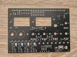
    I made the board design in OSHWLAB, manufacturing with component assembly in JLCPCB.

    This is what the TOP side of the board looks like
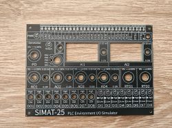
    Front panel of the SIMAT-25 simulator with printed descriptions of inputs and outputs. .

    And this is the BOTTOM side
    Top view of the PLC simulator main board.

    TOP side after installation of potentiometers, switches etc.
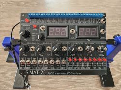
    SIMAT-25 PLC simulator with various knobs and displays on the control panel.

    And the BOTTOM side after making the connections. Spaghetti but unfortunately unavoidable.
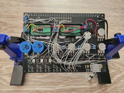
    Signal simulator circuit board with numerous components and connections. .

    Greetings! :) .

    Cool? Ranking DIY
    About Author
    Andrzej_Tomaszewski
    Level 13  
    Offline 
    Andrzej_Tomaszewski wrote 193 posts with rating 237, helped 2 times. Been with us since 2005 year.
  • ADVERTISEMENT
  • #2 21451639
    TechEkspert
    Editor
    WOW! super for PLC testing. Such a little HIL ;) or at least a convenient hardware parameter setter.

    Maybe there would be a chance for an article on FBD, what are your impressions and how to get started.

    Ew. maybe you would like to record a podcast together about PLC/FBD :) .
    https://www.elektroda.pl/rtvforum/audio.php
  • #3 21451727
    Andrzej_Tomaszewski
    Level 13  
    >>21451639 .
    Thank you.
    FBD reminds me very much of the time some 20 years back when I used to make schematics on a piece of paper, "on my knee" and FBD blocks were logic gates, flip-flops, timers, counters, registers based on the popular TTL 74 series. Only then it took a lot of time to make an uncomplicated circuit, not to mention the lack of flexibility in terms of modifications. Now it's a fairy tale. I draw the schematic, modify as I want and see how it works straight away. Thanks for the podcast/article suggestion. When I feel strong enough on the subject I'll get back to you:) .
    Regards
  • #4 21451791
    efi222
    Level 19  
    A beautifully crafted device.
    I was reminded of when I started working as an automation technician. Logic systems were built then in the German pneumatic system DRELOBA.
    Distributed logic in EX zones.
    Such a moment of nostalgia :) .
  • ADVERTISEMENT
  • #5 21451860
    elukam
    Level 16  
    I make such a thing for each non-unit manufactured separately. It makes setup and basic testing very easy. However, even such a dedicated tester, even with dedicated logic and analysis of selected protocols sewn in, works only in a basic way. For example, if you need specific signal values, you still need to use a professional class referencing device or referencing devices. Usually, a simulated object to be controlled is also needed and, in this case, "potentiometer and LED" logic is no longer sufficient, the properties of the object need to be accurately calculated and reproduced in the circuit, and this must work without contact in real time.
    If the author is satisfied with such a helper, then ok, but I would like to point out that it is not worthwhile to solder the cheapest Chinese connectors, because at this stage you can already become disgusted with the use of the tool.
    I would also add at least a basic integration facility with inertia, so that the energy invested is not wasted too much.
  • ADVERTISEMENT
  • #6 21451954
    Andrzej_Tomaszewski
    Level 13  
    elukam wrote:
    I make such a thing for myself for each non-unit manufactured separately.
    .
    Then please insert a photo of your design, at least one of what I'm guessing are many different pieces. Just for comparison.

    Andrzej_Tomaszewski wrote:
    I decided that I would design and make my own simulator. It was to be a compact design providing all the basic signals for the PLC under test.
    .
    This was the intention of this circuit and will remain so. It was intended to provide basic I/O signals for the purpose of testing a utility program for a PLC, where potentiometers, LEDs and switches are quite sufficient. For simple applications we use simple tools, for complex ones we use complex tools.
  • #7 21451977
    gulson
    System Administrator
    Amazingly this has come out. If I had seen it like that for the first time I would have thought it was factory equipment from some well known manufacturer ;) .
    Thanks for the presentations! I'll send something small to the Parcel Post.
  • #8 21452089
    Andrzej_Tomaszewski
    Level 13  
    Thank you :) .
  • #9 21452656
    elukam
    Level 16  
    Andrzej_Tomaszewski wrote:
    Yes for comparison.
    I don't photograph and by no means make my work public. But here I have an example of such a tester from 17 years ago, a photo taken as you might guess for a different reason :) I chose one on which you can see most of the panel surface.
    The tester is what is needed. Universal testers do not work in my opinion.
    Child in a green shirt operating a control panel with buttons and knobs. .
  • #10 21452694
    Andrzej_Tomaszewski
    Level 13  
    >>21452656 .
    Thank you for the photo.

    elukam wrote:
    Test is what is needed.
    - exactly right.

    Greetings
  • ADVERTISEMENT
  • #11 21452937
    pikarel
    Level 38  
    Instead of buying a tester - you made your own. Already a huge plus for just making one, another for the design and implementation at a high level. Everything in a pile, in one place.
    From the description I deduce that you added your own improvements to what was available "for a piniondze" :) .

    If the simulator is used even once - it has already served its purpose, but it follows that you are "in the subject" and will use it more than once.
  • #12 21452980
    Andrzej_Tomaszewski
    Level 13  
    >>21452937 .
    You put it very aptly. It was just supposed to be everything in a pile and in one place. What was available for sale did not meet my expectations, besides the price was too high in relation to the possibilities of the offered product, I mean dedicated simulators for LOGO! and S7-1200. Thank you for appreciating my work. Best regards to you :) .
  • #13 21457708
    electro
    Level 18  
    It looks great! But when fully assembled, the inside becomes a visual mess; if the paths were routed so that there was no need for a spider web of wires, just the shortest possible wires, it would be even better.
  • #14 21457973
    Andrzej_Tomaszewski
    Level 13  
    >>21457708 .
    Thank you:) Yes, it looks quite chaotic, but according to the design :) Your idea to locate the soldering points as close as possible to the switches which would allow the use of short wires I also analysed during the design. And unfortunately, because of the path-free area on the PCB that has to be provided for switches, potentiometers, displays etc. there is not enough space for routing further paths. Nevertheless, from the point of view of soldering the wires, it is the same job regardless of the length of the wires. Aesthetics suffer, of course, but ultimately the wires are well hidden. The most important thing is the solidity of the connections and the insulation of each other.
    Regards
  • #15 21460607
    goodbay
    Level 12  
    It looks great in person. Will definitely be useful for learning.
  • #16 21481660
    Andrzej_Tomaszewski
    Level 13  
    Welcome,

    I have prepared a video presentation of my simulator. The first 10 minutes is a discussion of the features of the device which I have already presented in the first post. From 10:35 I present some simple practical examples using all the capabilities of the simulator. I encourage you to watch the material.

    Regards


    .
  • #17 21481784
    TechEkspert
    Editor
    The video looks professional as does the design.
    What microphone did you use?
    Sometimes it's useful to use additional stage lighting.
  • #18 21481797
    Andrzej_Tomaszewski
    Level 13  
    Thank you, I recorded the whole thing with a Samsung Galaxy S23. Yes, the lighting is poor and for the future I will try to refine this. Regards

Topic summary

The discussion revolves around the design and implementation of a custom control object simulator for PLCs, specifically for Siemens LOGO! and S7-1200 models. The author shares their experience in PLC programming and the challenges faced when testing programs using physical components like switches and lights. They opted to create a compact simulator to facilitate input signal simulation and output state visualization, enhancing the testing process. Responses highlight the nostalgia of early automation work, the importance of quality in component selection, and the effectiveness of the simulator for educational purposes. A video presentation of the simulator was also shared, showcasing its features and practical applications.
Summary generated by the language model.
ADVERTISEMENT