logo elektroda
logo elektroda
X
logo elektroda

Creating a 9V Schmitt Trigger: Calculating Elements, Transistor Selection & Input Voltage

wienshu 8475 8
ADVERTISEMENT
Treść została przetłumaczona polish » english Zobacz oryginalną wersję tematu
  • #1 16446817
    wienshu
    Level 2  
    Hello all!

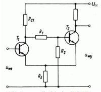
    I have a Schmitt trigger like in the diagram, with a supply voltage of 9V:

    Creating a 9V Schmitt Trigger: Calculating Elements, Transistor Selection & Input Voltage

    I am asking for advice on where to start calculating the trigger elements. I had read several articles before, including:

    Schmitt trigger and hysteresis loop

    however, I am still not quite sure where to start. Is it from the selection of transistors or from the input voltage of the T1 base?


    greetings
  • ADVERTISEMENT
  • #2 16447850
    jarek_lnx
    Level 43  
    What parameters do you want to get?
    What is it for?

    Usually, the design begins with the fact that we have some requirements that the system has to meet.
  • #3 16448249
    wienshu
    Level 2  
    The system will work as a twilight switch, and there will be a voltage divider at the input of the system - photoresistor and potentiometer.
  • ADVERTISEMENT
  • #4 16448383
    jarek_lnx
    Level 43  
    And what will be connected at the output?
    What is the approximate resistance of the photoresistor at which the system is to switch?
  • ADVERTISEMENT
  • #5 16448693
    wienshu
    Level 2  
    There will be one transistor controlling the relay on the output.
    For the voltage divider at the input, I used a 10k potentiometer and a GM25516 photoresistor (5 to 10k with 10 lx lighting).

    Using the diagram below:

    Creating a 9V Schmitt Trigger: Calculating Elements, Transistor Selection & Input Voltage

    the system works fine.

    Calculations of individual elements (resistors) can be found in the network but I do not know where to start all the calculations. What parameter starts and conditions further calculations?
  • Helpful post
    #6 16449250
    rb401
    Level 39  
    wienshu wrote:
    What parameter starts and conditions further calculations?


    In a very rough calculation of the circuit's switching points, it is assumed that the transistors have high current gain (i.e. their base current is negligible) and that they both have the same characteristics (mainly the voltage Ube).
    With these assumptions, looking at the circuit, we see a classic differential amplifier with a common emitter resistor (this is especially visible if we draw T2 with the base to the right).
    So the properties of such a system show that the key issue is the voltage difference between the bases.

    And it is at these moments when this voltage difference between the bases crosses zero that the differential amplifiers change from one conductive transistor to the other. And here in this system, additionally due to the positive feedback, there is a switch from one stable state to another (at the output).

    Since the base voltage T1 is the input voltage and it is given, the key issue in calculating the flip-flop characteristic is to find out what voltage is on the basis of T2 in both states of the flip-flop. Possibly what are the voltages on the T1 collector, because from this point we have the R1 / R2 divider.

    When the input voltage is lower than the lower switching threshold (T2 is conducting, T1 is not) the calculation is simple. We have an ordinary divider from three resistors Rc1, R1, R2 on the supply voltage and we can easily calculate the voltage on the basis of T2.
    So we have calculated "upper" voltage, when reached which the flip-flop switches to the state T1 conducts, T2 does not.

    A little more trouble with the "lower" voltage, but if we assume that R1 + R2 have a much greater value than Re, we have a series connected on the power supply Rc1, a saturated transistor T1 (i.e. around 0.5V) and Re. From this we calculate the collector voltage T1.
    From this calculated voltage, taking into account the divisor R1 and R2, we calculate the base voltage T2. This is the "lower" switching voltage of the flip-flop.

    It is true that this method of calculation is not very accurate, but in practice it is also difficult, due to the dispersion of parameters, to exactly hit the assumptions.

    You can see your layout live here:

    Schmitt simulation

    and move the Resistance slider to the right, specifying the input voltage, where the thresholds differ slightly from these approximate calculations. But this simulation is also an approximation.
  • #7 16449360
    CYRUS2
    Level 43  
    wienshu wrote:
    I am asking for advice on where to start calculating the trigger elements. however, I am still not quite sure where to start. Is it from the selection of transistors or from the input voltage of the T1 base?
    Dude, counting this Shmit trigger in your application is a complicated issue.
    Requires a lot of knowledge in electronic circuits.
    In addition, in this system everything depends on everything.

    You cannot count the diagram you have drawn. Because you have to additionally define input and load parameters.

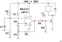
    Design your twilight switch on an operational amplifier.
    It's much simpler.
    Creating a 9V Schmitt Trigger: Calculating Elements, Transistor Selection & Input Voltage
    The circuit is very "flexible" in terms of the resistor value requirements.
    Calculations - trivial - you can do in memory.
    For design, the ability to use a voltage divider on resistors is enough.
    There may also be another type of op-amp.
  • ADVERTISEMENT
  • #8 16452959
    wienshu
    Level 2  
    rb401 thank you for the answer, that's what I meant ;)

    CYRUS2 thanks for the post, but I didn't mean to find an alternative, but to find the answer where to start with the layout I posted in the previous post ;)


    greetings
  • #9 16453012
    CYRUS2
    Level 43  
    wienshu wrote:
    CYRUS2 thanks for the post, but I didn't mean to find an alternative, but to find the answer where to start with the layout I posted in the previous post
    From the measurements of the photoresistor switch-off threshold.
    Switch-off threshold with connected measuring resistor.
    This circuit will not work with any resistor - because the circuit has poor input parameters.
    So it's a waste of work - there is no algorithm for calculation.
    Design the circuit on the operational amplifier.

Topic summary

The discussion revolves around designing a 9V Schmitt trigger for a twilight switch application, utilizing a voltage divider with a photoresistor and potentiometer. Participants emphasize the importance of defining system requirements and parameters before starting calculations. Key considerations include the selection of transistors, the input voltage at the base of T1, and the output load, which involves controlling a relay. Suggestions include calculating switching points based on voltage differences between transistor bases and the impact of positive feedback. Some participants recommend using operational amplifiers as a simpler alternative for the design, highlighting the complexity of calculations required for the Schmitt trigger configuration.
Summary generated by the language model.
ADVERTISEMENT