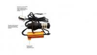
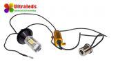
Welcome to all Colleagues in this forum. I recently bought and installed in my Scenic DRL lights in the direction indicators for daytime driving. Everything works, but I have a question for you. Where to get a "+" after the DRL power station? There is a box with relays and fuses in the engine compartment. There, it would be the closest and most convenient to mount the DRL off relay when switching on the position lights.
This is how a strip with relays and fuses looks like in this case: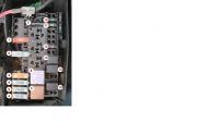
And underneath:
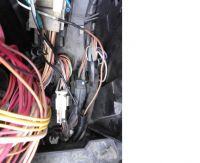
I was looking for yellow wires because they have a "+" after the ignition. In fuses and relays there is only "+" after the ignition switch on the coil and relay 13 of the fuel pump and on the 12 airbag and ASR power fuse. At first I joined the yellow orange wire in the joint of the larger white cube.
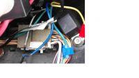
It turned out that this cable connects to the fuse 12. So I gave up this wire. I am afraid of any disturbances to the airbag or ASR. I shoved the yellow coil of the fuel pump relay coil. Only there is one! Will it not be an extra charge? The cable is quite thin. Here I have diode data mounted in these bulbs:
Smd LED 4014 - 6800K
Brightness 22- 28 lm
IF 60mA
VF- 2.3-3.4V; 0,2W
Cri 80
One light bulb has 30 white and 30 yellow LEDs. So 60 diodes (daylight) or 30 yellow (direction indicators) are lit at once.
From this it would seem that one bulb has 6W. So both have 12W power. So how many of these bulbs are pulling amps? 3.6A (60pcs x 60mA)? But is it possible? There is a 2A fuse on the circuit protection. What does not it crash?
So how to do it? Directly connect to the pump relay coil power supply cable? Can it, however, through the second relay and then "+" take it directly from the aku? Is there any sense to do something like that? Can these DRLs really interfere with the proper operation of the pump relay coil?
I checked the voltage at the relay contacts of the pump. There is a fixed + on one contact. So it's gone. On the second when I apply the meter to the coil supplying wire a - to - aku the meter shows voltage but with -. After connecting + DRL, the bulbs do not shine under this cable.
This is how a strip with relays and fuses looks like in this case:

And underneath:

I was looking for yellow wires because they have a "+" after the ignition. In fuses and relays there is only "+" after the ignition switch on the coil and relay 13 of the fuel pump and on the 12 airbag and ASR power fuse. At first I joined the yellow orange wire in the joint of the larger white cube.

It turned out that this cable connects to the fuse 12. So I gave up this wire. I am afraid of any disturbances to the airbag or ASR. I shoved the yellow coil of the fuel pump relay coil. Only there is one! Will it not be an extra charge? The cable is quite thin. Here I have diode data mounted in these bulbs:
Smd LED 4014 - 6800K
Brightness 22- 28 lm
IF 60mA
VF- 2.3-3.4V; 0,2W
Cri 80
One light bulb has 30 white and 30 yellow LEDs. So 60 diodes (daylight) or 30 yellow (direction indicators) are lit at once.
From this it would seem that one bulb has 6W. So both have 12W power. So how many of these bulbs are pulling amps? 3.6A (60pcs x 60mA)? But is it possible? There is a 2A fuse on the circuit protection. What does not it crash?
So how to do it? Directly connect to the pump relay coil power supply cable? Can it, however, through the second relay and then "+" take it directly from the aku? Is there any sense to do something like that? Can these DRLs really interfere with the proper operation of the pump relay coil?
I checked the voltage at the relay contacts of the pump. There is a fixed + on one contact. So it's gone. On the second when I apply the meter to the coil supplying wire a - to - aku the meter shows voltage but with -. After connecting + DRL, the bulbs do not shine under this cable.


