logo elektroda
logo elektroda
X
logo elektroda

Wiring a 7.5 kW Compressor Switch: Guidance on L3, A2 and Coil Bridging

marcin9791 13956 19
ADVERTISEMENT
Treść została przetłumaczona polish » english Zobacz oryginalną wersję tematu
  • #1 16535172
    marcin9791
    Level 10  
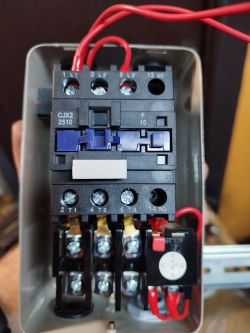
    Hello, I need professional help on how to connect the compressor compressor main switch exactly. With L1 it is released on the switch, what are these 2 free cables (blue) for L3 and A2, do you need to bridge the coil?
    For one phase will the coil go?
    I attach photos:
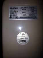
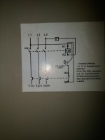
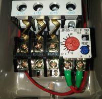
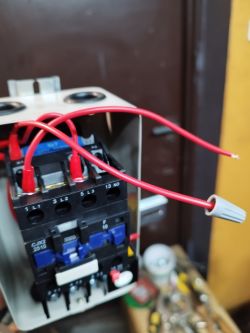
    Wiring a 7.5 kW Compressor Switch: Guidance on L3, A2 and Coil Bridging20170617_1..506.jpg Download (3.31 MB) Wiring a 7.5 kW Compressor Switch: Guidance on L3, A2 and Coil Bridging20170617_1..333.jpg Download (3.64 MB) Wiring a 7.5 kW Compressor Switch: Guidance on L3, A2 and Coil Bridging20170617_1..318.jpg Download (4.03 MB) Wiring a 7.5 kW Compressor Switch: Guidance on L3, A2 and Coil Bridging20170617_1..350.jpg Download (3.56 MB)
  • ADVERTISEMENT
  • #2 16535349
    beam_beer
    Level 23  
    In the first picture you have a photo of the contactor with a 380 V coil, i.e. phase-to-phase, i.e. you will not supply this contactor with one phase.
    Blind blue wires stick out because someone had such a fantasy. Nothing comes of it.
    On the following photos you have a diagram, and connected components according to this diagram.

    And what do you want


    Jaaaaajććć ...

    Sorry, these are photos of the same mailbox.
    Between these 2 blue should be plugged pressure switch that controls all this.
    If you short these 2 blue ones, you turn them on, but nothing turns you off, there must also be a pressure switch.
  • ADVERTISEMENT
  • #3 16535518
    marcin9791
    Level 10  
    The switch goes from L1 top and on the thermostat, L3 released the cable and A2 by default, so I don't know what's going on, the pressure switch has an output next to the thermostat, and can someone explain how to connect the top?
  • Helpful post
    #4 16535552
    beam_beer
    Level 23  
    L1, L2, L3 supply to L1, L2, L3 on the contactor, blue blinded to the pressure switch.
    I don't tell you anymore, because if you don't start after this post, it's better not to do it.
  • #5 16535565
    marcin9791
    Level 10  
    No, the pressure switch goes to these 3 phases lower at the thermostat to the left of the red knob from amps. How can I push 2 blue plugged cables on the pressure switch, in the diagram as if you can see that A2 is bridged with L3
  • #6 16535581
    nikusert
    Level 41  
    Hello.
    Connect the pressure switch as prompted by a colleague Beam_beer. Upper clamps; L1, L2, L3 are power supply, lower terminals output for the motor.
    Of course, when connecting the power supply you can not forget about the PE protective conductor.
  • #7 16535586
    marcin9791
    Level 10  
    I understand, the ground screw is on the housing.
    A designation A1 (connected to the red thermal)
    A2 (released blue)
    What do these A1, A2 mean
    I don't sit too much in electricity, but something must be A2 blue :)
  • Helpful post
    #8 16535625
    nikusert
    Level 41  
    A1, A2 - on the contactor, are the contactor coil terminals. These two blue ones connect to the pressure switch.
    The control is yes;
    The L1 phase comes to the L1 power supply terminal, it goes to the circuit breaker
    - a thermal break comes from the switch
    - from the thermic goes to A1 (contactor coil clamp)
    - from the L3 terminal (to which the supply L3 phase is connected) the wire goes to the terminal A2 of the contactor coil
    The coil is powered between phases (400V) as previously written by colleagues.
  • #9 16535649
    marcin9791
    Level 10  
    So L1, L2, L3 connect the power supply, A2 link with L3
    A bottom for a pressure switch (3 phase pressure switch)
    ??
  • #10 16535672
    nikusert
    Level 41  
    No.
    With a 3-phase pressure switch, you use one pair of contacts to which you connect the blue wires insulated with plastic plugs.
  • ADVERTISEMENT
  • #11 16535693
    marcin9791
    Level 10  
    Strange because the bottom is the output for a pressure switch through a thermostat
    Wiring a 7.5 kW Compressor Switch: Guidance on L3, A2 and Coil Bridging
  • #12 16535715
    nikusert
    Level 41  
    A thermostat is connected to the contactor output, and a motor is connected to the thermostat output.
  • #13 16535725
    marcin9791
    Level 10  
    That's where I release the pressure switch (pressure switch) and the pressure switch on the engine.
  • #14 16535758
    nikusert
    Level 41  
    Can you do that but?
    In this case, the blue wires must be connected to each other. In this system, the contacts of the pressure switch, which is probably more expensive than the contactor you have used, suffer unnecessarily.
    I would do as I write (the pressure switch controls the contactor), do as you like.
  • #15 16535769
    marcin9791
    Level 10  
    So I didn't think wrong, I understand it more or less
    Thanks a lot if I speak to you :)
  • #16 16539684
    marcin9791
    Level 10  
    I connected as described above, everything works fine, sorry for the misunderstanding and thank you very much for your help
    Regards
  • ADVERTISEMENT
  • #17 16539696
    nikusert
    Level 41  
    No problem, it's worth helping.
  • #18 16539819
    marcin9791
    Level 10  
    Exactly :)
  • #19 20466859
    kamilq
    Level 10  
    Hello. A little digression, but I have the same problem. I have a similar contactor, although the original connections are a bit different. The power and motor connections are clear. Where should I connect the pressure switch? Under the coil A1 and L1 as it is originally derived? Then coil A2 remains free.
    Wiring a 7.5 kW Compressor Switch: Guidance on L3, A2 and Coil Bridging Wiring a 7.5 kW Compressor Switch: Guidance on L3, A2 and Coil Bridging
  • #20 20466993
    nikusert
    Level 41  
    If you connect A1 with the L1 wire, does the contactor work?
    The other terminal A2 is at the bottom of the contactor.
    One wire from the thermal switch is connected to it (auxiliary contact), the other wire is connected to L3.

Topic summary

The discussion revolves around the proper wiring of a 7.5 kW compressor switch, specifically addressing the connections for L3, A2, and coil bridging. Users clarify that L1, L2, and L3 are the power supply connections to the contactor, while A1 and A2 are the coil terminals. The blue wires are intended for the pressure switch, which should be connected to control the contactor. It is emphasized that the coil requires a phase-to-phase connection (400V) and that the pressure switch must be integrated correctly to ensure proper operation. The final consensus confirms that the wiring setup works effectively when followed as described.
Summary generated by the language model.
ADVERTISEMENT