logo elektroda
logo elektroda
X
logo elektroda

Repair of the impulse power supply in the Alesis M1 Active Mk2 column

waran3 19713 21
ADVERTISEMENT
Treść została przetłumaczona polish » english Zobacz oryginalną wersję tematu
  • #1 16620577
    waran3
    Level 12  
    Hello, :-)
    The loudspeaker has been damaged:
    Alesis M1 Active Mk2.
    The power supply has fallen, many components have been damaged, but they are available for purchase.
    The TDS-1196 transformer also works in the power supply.
    I have a suspicion that it may be damaged, and there will be trouble buying it.
    (the transformer turned out to be in working order)

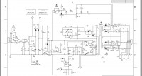
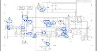
    Is anyone able to estimate on the basis of the diagram (attached)
    what inductance should the primary windings have? I would like to diagnose him this way.

    Unfortunately, the transformer is an Alesis product and its parameters are nowhere to be found.
    I did send an inquiry to the manufacturer, but so far no answer.
    If this is not possible, the second column is functional, but I would like to avoid desoldering it :-)

    The second fundamental question is, is it possible to somehow define the parameters of this transformer, so that it can be replaced with something else, or made independently?
    I would like to add that the damage occurred when the loudspeaker was turned on.
    My house fuse has blown :-)

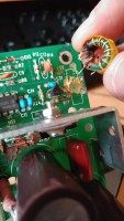
    As a result, I was able to diagnose that the transistors controlling the transformer: Q1 and Q2 flew. Resistor R15 is all black and because it sits near the transformer, the latter is also blackened. After desoldering the transformer, it turned out that one wire is broken (burnt?) Right next to the soldering point to the transformer's leg. All transformer circuits are conductive. Unfortunately, I cannot determine whether the scorch was caused by the burning of the resistor, or if the transformer winding was also on fire.
    The transistors controlling the Q1 transistor, i.e. Q3 and Q4, are also damaged. Of course, there were also diodes from the Graetz bridge D1 - D4

    I also have a general question. What is the most common cause of this type of damage - breakdown of power transistors? Is the transistor simply dropping out of old age (wear)?
  • ADVERTISEMENT
  • #2 16620659
    SERVICE-AV
    Level 39  
    Transistors do not wear out :)
    There had to be an external cause (mains overvoltage - most likely the cause) or a fault on the primary part of the inverter.
  • Helpful post
    #3 16621010
    jarek_lnx
    Level 43  
    A moment after the transistor is damaged, a huge current flows in the circuit, burning the diodes in the bridge and the resistor-shunt R15 is typical, after burning R15 through the shorted transistor Q1, the voltage damaged the Q3 and Q4 buffer, sometimes the controller (UC3844) is damaged.

    Quote:
    After desoldering the transformer, it turned out that one wire is broken (burnt?) Right next to the soldering point to the transformer's leg. All transformer circuits are conductive. Unfortunately, I cannot determine whether the scorch was caused by the burning of the resistor, or if the transformer winding was also on fire.

    Burning the transformer is unlikely, it takes time, and the short-circuit current in this system flows very briefly and there are much more delicate elements in the circuit, which are damaged faster, interrupting further current flow.
    You can tell a broken wire from a burnt one, the melted ends look completely different.
    It is normal that the transformer for DC has very little resistance, there is little wire in it.
  • ADVERTISEMENT
  • #4 16621251
    waran3
    Level 12  
    SERVICE-AV wrote:
    Transistors do not wear out

    I know :-) but I meant something like overheating or something.

    jarek_lnx wrote:
    Burnout of the transformer is unlikely

    I thought so too (it would suit me). :-) But it did
    to head that maybe this transformer is the cause of the whole incident (short circuit between the turns - although this is also unlikely, I think). The cable was strangely broken, so I have my suspicions about it. Well, maybe
    I broke it off during disassembly, and I'm sticking to it for now. : -)
    There must be a reason, because I don't think the electrolytes would have caused it, I already replaced them.
    jarek_lnx wrote:
    sometimes the controller is damaged (UC3844)

    Thanks for that note. I will buy this chip just in case, because now I am not able to diagnose it.
  • #5 16623914
    waran3
    Level 12  
    I was able to locate all the damaged items.

    4 LEDs in the Graetz bridge
    U1 UC3844N chip

    Transistors:
    Q3 2N4401
    Q4 2N4403
    Q1 and Q2 - IRF840
    Resistor R15 - 0.22 Ohm

    I also replaced electrolytes.
    C6, C7, C8, C35

    As a result, I managed to bring the LED indicating the voltage on. I turned on the music, the loudspeaker started to play and it creaked, crashed and tripped the fuse in the house again.

    I mean, the cause has not been removed.
    I would be grateful for your suggestions.
  • Helpful post
    #6 16624095
    SERVICE-AV
    Level 39  
    Measure the areas responsible for controlling the output voltage - TL431, optocoupler and all the small items around them. Capacitors for pin suppression in Q3 / Q4 bases. Accurate measurement of all general cargo, especially on the primary side :)
  • #7 16625789
    waran3
    Level 12  
    So far, the entire bridge has been damaged, but the Q1 and Q2 transistors managed this time. :-)
    Same with Q3 and Q4 - working.
    I think the fuse burned earlier (5A)
    I don't know about the UC3844N, but I bet that since these elements worked well, he had no reason to burn himself.

    The vicinity of the optocoupler seems approx.

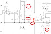
    However, I found a punctured diode D14 (Q2 drain). I don't know if it has fallen now or earlier, because it's a new discovery. I also cannot determine if it could have been the cause of the second short circuit. I admit that I do not know what exactly it does with this C40 capacitor, it looks like a filter :-)
  • #8 16804184
    waran3
    Level 12  
    I was able to repair the power supply :-)
    I will post a detailed description soon.

    Because the repair of the first column took quite a long time (I was learning switching power supplies) :-) it has fallen
    also the second.

    In the case of the first repair, probably all the semiconductors that work on the primary side of the power supply burned out, and one
    after the secondary.
    My general remark is that one damaged element is enough and the entire power supply goes up in smoke, so I recommend preventive replacement of electrolytes to all who still use this set:
    c6 and c7 - 390 uF / 200V - they are probably the main cause of failure
    c35 - 1uF / 50V
    c7 - 330?F / 35V (on the diagram 220?F, but originally it was 330?F)
    Repair of the impulse power supply in the Alesis M1 Active Mk2 column

    On the internet, people suggest replacing anti-interference capacitors as well
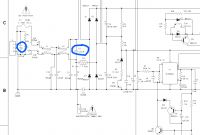
    c1 and c2 - 0.22 uF / 275V
    Although in my opinion it seems superfluous (but I have replaced them at home).
    Repair of the impulse power supply in the Alesis M1 Active Mk2 column

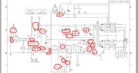
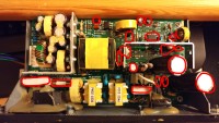
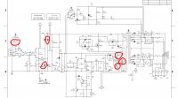
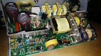
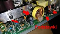
    The elements that were damaged in the case of the first column are marked below.
    I would like to point out, however, that I learned there and made a short circuit many times.
    Repair of the impulse power supply in the Alesis M1 Active Mk2 column

    It went better with the second column, but the damage was not much less.
    Repair of the impulse power supply in the Alesis M1 Active Mk2 column
    In the case of the second Alesis, I replaced the TL431 (u3) chip, without knowing whether it is functional or not. He was in the first column
    100% damaged, but I do not know at what point it happened, whether immediately or later at any attempt to start the power supply.

    Going in turn.
    After the first short circuit, it tripped a fuse in the house.
    I reconnected the column at least one more time, not sure what I was counting on, causing a short circuit again. :-)
    I am writing about this because the first Alesis had a blown fuse, and the second one was not. The fuse in the house was faster :-)
    I have already written about anti-interference capacitors, I only mentioned them as a precautionary measure.
    Thermistor RT1 burnt a bit after a few short circuits (column 1), so I replaced it.
    The D1-D4 bridge in the first column burned several times, in the second one only the D1 and D2 diodes burned out.
    Unfortunately, when Q1 breaks through, Q3 and Q4 also burn, the same goes for Q2 and Q5.
    The biggest surprise for me was the damage to the T2A choke, both in both columns. In the first one there was smoke coming out of it at some point, and in the second the coils were burnt, causing some short circuits and, as a result, bad operation of the power supply. I rewound the first choke (with the same wires), and in the second one, I parted the wires a bit in the visible spot of the burn, so that they wouldn't touch each other, and poured glue over them.

    When the UC 3844N (U1) is on, I do not know, but I had to replace it in both loudspeakers, although in the second I am not sure if it was necessary, because after replacing it, the power supply was still defective and only repairing the T2A brought the expected result.

    There is also the R15 resistor, which was simply black in the first column, probably because of the number of short circuits that closed through it. In the second, it was slightly darkened. I do not know if as a result of normal operation or if it caused a short circuit. Anyway, I soldered a new 2W resistor.

    Since the power supply cannot be repaired gradually, because it either burns or works well, it is a good idea to use a traditional 100 W bulb instead of the fuse. It significantly reduces the current, so that nothing burns, and on the other hand, the whole system works almost normally. In addition, the behavior of the bulb light serves as an indicator of the power supply operation.
    If everything is ok, the bulb will light for a moment and then go out completely.
    Then you need to check the voltage at the output of the power supply.
    The two extreme pins of the J5 socket are the voltage above 60 V. If it is, then the power supply is operational at 99%.
    The light bulb may catch on, go out, and then flash brighter and brighter. If we do not turn off the power in time, transistor Q1 will burn out (despite the presence of the light bulb). In my case (column 1), the UC3844N chip and transistors Q7 and Q6 turned out to be damaged.
    In the second column, the light bulb went out, but there was no output voltage. Transistor Q5 turned out to be damaged. After replacing it, the voltage appeared, but the bulb was blinking slightly and here the cause was a burned T2A choke. In addition, once it was good and bad, and that made me take a closer look at this choke, because at first I ignored its burning (it was not so obvious).

    Currently, both loudspeakers work as before and enjoy my ears with a very good sound. :-)
    And that was probably about it.

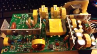
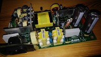
    I am attaching a few more photos from the repair and a video:
    [movie: e3ae3be77b] https://filmy.elektroda.pl/93_1510078183.mp4 [/ movie: e3ae3be77b]
  • ADVERTISEMENT
  • #9 16810644
    waran3
    Level 12  
    Unfortunately, the first loudspeaker burnt again, so it seems that the cause is still not eliminated.
    The only difference is that the fault has already occurred during operation, and not during switching on as before.
    The following elements were burnt:
    Repair of the impulse power supply in the Alesis M1 Active Mk2 column

    Transistors Q1, Q3, Q4
    D2 and D3 diodes
    Fuse

    Unfortunately, something is still damaged because the power supply does not work, i.e. it works, but as if it is swinging with power, the diode lights up, fades over and over again. The speakers crackle.
    I replaced the UC3844N and TL431 chips just in case, but that didn't do anything.
    Q1 gets very hot and I don't know if it should be like that, because I didn't control it before.
    For now, I am thinking and asking for some suggestions.

    Today I replaced all the electrolytes on the secondary side of the power supply, unfortunately to no avail.
    I have observed a strange phenomenon. At the moment of turning off the switch, you can hear such a "puff"
    and there is a good voltage on the output for a moment.
    During one attempt, the power supply surprised, but I could hear such a puff (every 1 second) that came from the transformer in my ear. It popped, popped, and suddenly it stopped popping, the output voltage dropped and the heat sink from Q1 and Q2 started to heat up very much again.
  • #10 16826232
    waran3
    Level 12  
    I sat a bit on the power supply again and it turned out that I did a good number.
    Instead of Q3 I soldered the TL431 chip, they have the same housings.
    No wonder the power supply was behaving bizarrely.

    After soldering the appropriate transistor at the output (pins 1 and 6 - that's what I made a reference point for a properly functioning power supply - about 63 V), an extremely high voltage, over 100 V, appeared and the converter froze. It turned out that transistors Q3 and Q4 were burned out.
    After replacing the transistors, the converter does not start, because the supply voltage on pin 7 of the UC3844 chip is within 12 V.
    Now I am fooled about it. I replaced almost everything and the power supply still won't work.
    Please give me some suggestions.

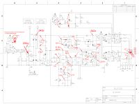
    In the meantime, I applied the measured voltages (multimeter - I do not currently have an oscilloscope) in a properly working power supply. Most of the tensions have been measured against mass.
    Places where otherwise are marked with two arrows respectively.
    Repair of the impulse power supply in the Alesis M1 Active Mk2 column

    Added after 19 [hours] 32 [minutes]:

    I was finally able to start the power supply today.
    In an act of desperation, I soldered the sockets for elements that are the most difficult to desolder (even transistors).
    I did so because I had parched paths in several places.
    It turned out that connection problems have started, and this is a short circuit, and that is a lack of connection.
    The tile looks like it has exploded. I left a few elements on the print side so as not to re-solder them.
    In sum, the power supply worked.
    Repair of the impulse power supply in the Alesis M1 Active Mk2 column
    Repair of the impulse power supply in the Alesis M1 Active Mk2 column

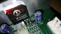
    Unfortunately, this is not the end of problems, it turned out that there is a short circuit in the amplifier itself. The LM3886T chip is damaged (short circuit in the power supply).
    Repair of the impulse power supply in the Alesis M1 Active Mk2 column
    This probably caused the column (power supply) to be damaged again.
    But what is the cause of damage to the amplifier now?
    For now, I will replace the integrated circuit.
  • #11 16832692
    waran3
    Level 12  
    Repair of the impulse power supply in the Alesis M1 Active Mk2 column
    Repair of the impulse power supply in the Alesis M1 Active Mk2 column

    Today (Saturday) comes the parts, wow! TEM really does the job. :-)
    I ordered the LM3886T and the electrolytes that work with this chip. I thought about electrolytes because z
    after some time there are always problems with them, and I do not know why the loudspeaker fell down again a few days after the repair of the power supply.
    Anyway, I replaced a few of these capacitors.
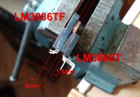
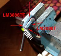
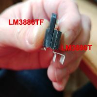
    As for the chip, as usual, I hit the blunder and instead of the LM3886TF I ordered the LM3886T without the letter "F".

    Repair of the impulse power supply in the Alesis M1 Active Mk2 column
    Repair of the impulse power supply in the Alesis M1 Active Mk2 column
    Repair of the impulse power supply in the Alesis M1 Active Mk2 column

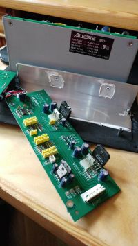
    A cosmetic difference, and it cost me running around shops and looking for thermo-conductive pads.
    This TF version has an insulated heat sink, the one without "F" does not.
    After replacing the elements, I checked the output voltage of the power supply to be sure.

    The voltage V_LO is - 24 and + 21 V, respectively, and V_HI is + 40 V and - 35.5 V.
    The higher voltage was on pin 6 (+ 40V) and pin 1 (- 24V)
    I admit that I do not know where these differences in symmetry come from, or in fact the lack of it.
    Anyway, I assumed it was ok and connected the amplifier - it worked! :-)
    So far, the column is working properly.
  • ADVERTISEMENT
  • #13 16855317
    sypky
    Level 1  
    @ waran3, it looks like I ran into the same problem. I also replaced half of the power supply on the primary side many times, after which the semiconductors burned after two / three days :D
    I haven't figured out what's wrong with me yet, but having the repair process described by you at my disposal, it will be much easier for me.
    An interesting clue is the t2 choke, although it does not look damaged for me, I think I will rewind it.
    As the post is quite fresh, I wanted to ask if the columns are still working? (I keep my fingers crossed for that).

    I wonder what is really causing the failure - people report similar problems online.
  • #14 16855561
    waran3
    Level 12  
    The columns work :-)
    I don't know exactly what caused the second column failure, but I suspect maybe TL431.
    Information about the output voltage goes through the optocoupler, but that's just a guess.
    Maybe one of the new elements was hit, because it was, for example, faulty, I don't know.
    I think that the voltage went too high for the amplifier, so the circuit showed a short circuit on the power legs.

    In general, aging electrolytes are likely to cause damage to the power supply.
    This is a common ailment of switching power supplies and not only power supplies.
    The more that the columns are firing at about the same time, this was the case with me (about 30 days apart)
    In my opinion, capacitors must be replaced absolutely, but I have already written about it.
    In this column that fired again after a while, I also replaced the electrolytes on the secondary side of the power supply and even
    those that work together with the amplifier in the low frequency path.
  • #16 17257863
    strato
    Level 15  
    I have just encountered the same problem - one of the speakers stopped working, i.e. it does not turn on. The best thing is that you can see absolutely no damage, burns, etc., the fuse is good, some difficulty will be desoldering elements in double-sided printing and flooded with something. Electrolytic capacitors for blind replacement, I have a converter built classically on 3842, but ... I was interested in the final damage to the tip. Did you manage to find out with the given voltages or let's say "ohmic"?
    Thanks for the excellent description of your struggles with this power supply without coloring and "not being ashamed of your own mistakes" that each of us makes, but not everyone can say about it publicly :sm9: and very good photographic documentation and legible diagrams.
  • #17 17257972
    Justyniunia
    Level 36  
    Maybe I won't help, but ...
    A few years ago, a colleague in his studio had identical matches with his Alesis. We then built an ordinary power supply for them on a transformer, rectifier and capacitors and the problem disappeared. There is extra stuff under the desk - that's a fact, but knocking on everything is already a long time.
    Apparently they even sound better now ;)
  • #18 17258195
    waran3
    Level 12  
    strato wrote:
    I have just encountered the same problem - one of the speakers stopped working, i.e. it does not turn on. The best part is that absolutely no damage, no burns etc. can be seen, the fuse is good

    If even the diode is not lit, and the fuse is intact, it is certain that there is no short circuit, but there is some break.
    My friend had a damaged choke, I think this L4, but it was blowing smoke, because there was some kind of cold solder.
    Overall the choke was not conductive, or rather acted like a resistor.
    It is difficult to say something like that, but 99% of semiconductors short-circuit during a failure. Well, unless the short circuit is somewhere outside the main circuit.
    It's still worth checking the UC3844, because it supposedly can break just by itself. I recommend putting a new one in the stand.

    As for the damage to the power amplifier, from what I remember, the short-circuit protection worked and the power supply did not start.
    It was enough to disconnect the cable that connects the power supply with the amplifier and the power supply was started.
    Then there was an ohmmeter and a short circuit was found.
  • #19 17259252
    strato
    Level 15  
    Cool, thanks for the suggestions. We'll see what happened, so far I've roughly measured the various conductors and other items. I approach the desoldering of the double-sided plate like a hedgehog, but the elements look ok, even the plate looks completely new, no burns.

    As I wrote earlier, I replaced the filtering capacitors behind the bridge, although the measured capacities did not differ much from the rated ones, and the 3842-C35 1uf / 50V and C8 330uF / 35V capacitor improving the operation, the small "fast" diode D5 BAVP21 was also short, other damage I have not found. After being turned on first by the light bulb, all the output voltage appeared - the system works.
  • #20 17535269
    waran3
    Level 12  
    The first column shot again after almost a year of impeccable work. The same when switching on and the fuse in the house also blown out.
    The one in the power supply did not budge.
    Burnt bridge (3 LEDs) and Q1, I'm sitting and picking. It's a bit annoying.
    Burnt Q3 and Q4 and UC3844N - God, thank you for the coasters!
    Column game!
    The question is why did she burn down again?
    Someone hinted that it might be a disturbance from the mains.
    I accept this translation this time. The left loudspeaker is powered by a suppression bar, and the right loudspeaker was connected directly to the socket, so maybe it is actually some kind of impulse. Although I admit that it does not convince me somehow,
    because the power supply has its filtering elements.

    This failure irritated me so much that I bought new monitors :-) Fluid Audio FX8.
  • #21 17547360
    mmatwiejszyn
    Level 2  
    I have damaged: D1, D2, D4, U1, Q1, Q3, Q4, R15 and finally fuse F1.
    I found the reason - C8, instead of 220 uF it had 105 uF (85 ° C) - I changed it to 330 uF / 50V 105 ° C. I also read that it should be good and solder on long legs to keep it away from R3, R4 and the heat sink Q1 and Q2, it will work maybe longer, 5+ years. U1 into the cradle. I recommend leaving the R15 power at 1 W, if it burns, it will burn, not luck. F1 - 5 A, no more.
  • #22 17750486
    waran3
    Level 12  
    I will add a very important thing. Problems with repair may also result from the fact that there are a lot of counterfeit items on the market.
    Even when buying in seemingly certain stores, we do not get a guarantee of originality.
    This turns repair into a true unpredictable lottery game.

    Justyniunia wrote:
    Maybe I won't help, but ...
    A few years ago, a colleague in his studio had identical matches with his Alesis. We then built an ordinary power supply for them on a transformer, rectifier and capacitors and the problem disappeared. There is extra stuff under the desk - that's a fact, but knocking on everything is already a long time.
    Apparently they even sound better now ;)

    I came across this description looking for clues, but I insisted on repairing the original power supply.
    It took a lot of time and money, but now I'm unbeaten when it comes to switching power supplies :-)
    When it comes to changing the sound, I am skeptical about this type of improvement.

Topic summary

The discussion revolves around the repair of the Alesis M1 Active Mk2 loudspeaker's impulse power supply, which suffered damage to various components, including transistors, diodes, and capacitors. Users shared their experiences diagnosing and replacing faulty parts, such as the UC3844N chip, TL431, and electrolytic capacitors. The importance of preventive maintenance, particularly the replacement of aging electrolytes, was emphasized as a common cause of failures. Suggestions included measuring critical areas in the circuit, checking for short circuits, and considering alternative power supply designs. Some users reported success in repairs while others faced recurring issues, indicating potential underlying problems with the power supply design or component quality.
Summary generated by the language model.
ADVERTISEMENT