logo elektroda
logo elektroda
X
logo elektroda

T.amp TSA 4-1300 Power Amplifier Issue: Not Turning On, Red Diode Flashing, No Visible Damage

Matek920605 71106 346
ADVERTISEMENT
Treść została przetłumaczona polish » english Zobacz oryginalną wersję tematu
  • #1 18261715
    Matek920605
    Level 10  
    Hello
    I am the owner of the T.amp tsa 4-1300 power amplifier
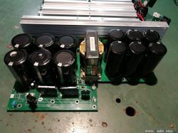
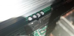
    The problem is that the tip won't turn on. After unscrewing the housing and measuring the voltage to the switching power supply, I noticed that the red diode mounted next to the capacitors was flashing. I will add that the fuse is intact. You can not see any burnt elements, the capacitors are whole .. I did not dismantle any further, because maybe some of you know the subject and do not want to unscrew the entire amplifier. I need help what could have ended in this ending here.
    Regards

    Added after 6 [hours] 15 [minutes]:

    Attached I will provide a link to a movie with an identical T.amp, where there is the same problem, to show what I mean exactly.
    https://www.youtube.com/watch?v=-p8wrjf3Rd0
  • ADVERTISEMENT
  • #2 18263559
    Matek920605
    Level 10  
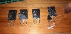
    I pulled out the entire motherboard, the IRGP 4066D transistors literally fired
  • ADVERTISEMENT
  • #3 18263644
    jozgo
    Level 42  
    Do you have a diagram or service manual for it?
    I have not seen on the internet.
  • #5 18263832
    jozgo
    Level 42  
    Unfortunately, it is a User Manual, i.e. a user manual, not a service manual.
    Maybe someone has. Because not having it on the table and not having a pattern means reading coffee grounds.
  • #6 18263901
    Matek920605
    Level 10  
    Exactly, I looked at the entire board carefully, only these transistors are damaged, the capacitors are complete, all paths are ok. The power amplifiers on each of the 4 channels are also functional. I can send photos of the whole album if I can

    Added after 8 [minutes]:

    T.amp TSA 4-1300 Power Amplifier Issue: Not Turning On, Red Diode Flashing, No Visible Damage
    In the evening I will send more detailed ones

    Added after 30 [minutes]:

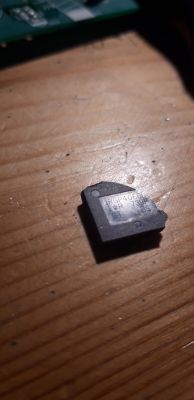
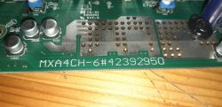
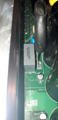
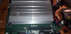
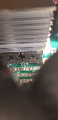
    photos before removing the heatsink with IRGP transistors removed T.amp TSA 4-1300 Power Amplifier Issue: Not Turning On, Red Diode Flashing, No Visible Damage T.amp TSA 4-1300 Power Amplifier Issue: Not Turning On, Red Diode Flashing, No Visible Damage T.amp TSA 4-1300 Power Amplifier Issue: Not Turning On, Red Diode Flashing, No Visible Damage T.amp TSA 4-1300 Power Amplifier Issue: Not Turning On, Red Diode Flashing, No Visible Damage T.amp TSA 4-1300 Power Amplifier Issue: Not Turning On, Red Diode Flashing, No Visible Damage T.amp TSA 4-1300 Power Amplifier Issue: Not Turning On, Red Diode Flashing, No Visible Damage

    Added after 4 [minutes]:

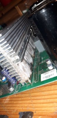
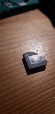
    removed heat sink and transistors that are in the same row as the damaged IRGP are mounted on the same heat sink
    T.amp TSA 4-1300 Power Amplifier Issue: Not Turning On, Red Diode Flashing, No Visible Damage T.amp TSA 4-1300 Power Amplifier Issue: Not Turning On, Red Diode Flashing, No Visible Damage [img-2] T.amp TSA 4-1300 Power Amplifier Issue: Not Turning On, Red Diode Flashing, No Visible Damage

    Added after 10 [minutes]:

    additionally, photos in the attachment
  • #7 18265716
    Matek920605
    Level 10  
    What made these transistors fire?
  • #8 18265750
    Anonymous
    Level 1  
  • ADVERTISEMENT
  • #9 18265793
    Matek920605
    Level 10  
    that is, as if some resistor refused to obey .. only by the eye you can not see any resistor that would be connected to them, only what is this MKKP82 capacitor

    Added after 22 [minutes]:

    I personally suspect a transormator .. there is only a problem because there is no serial number on this current one .. I see transistors for 600V
  • #10 18265853
    398216 Usunięty
    Level 43  
    Due to damage. :) And where this damage has occurred, it would have to be checked. It is possible that the transistor itself was not fully functional, it is possible that for some reason it was overloaded, or ... overheated.

    Added after 1 [minutes]:

    Matek920605 wrote:
    I personally suspect a transormator.
    TRANSFORMER - like the captain of the ship; comes down last.
  • ADVERTISEMENT
  • #12 18265899
    Anonymous
    Level 1  
  • #13 18265920
    Matek920605
    Level 10  
    there is no integrated circuit in the area, just more transistors behind them, but this is shown in the picture. they are marked: GBJ3006SF, 2506SF, 2x APT60D060BG

    Added after 2 [minutes]:

    https://www.youtube.com/watch?v=Le80PIi-yMs
    in this video the guy pretty much shows exactly what's inside.
  • #14 18265926
    Anonymous
    Level 1  
  • Helpful post
    #16 18265973
    Anonymous
    Level 1  
  • #17 18266017
    Matek920605
    Level 10  
    cool, I think my eyesight is poor :D Thanks for your help, I order parts and start replacing, I only have a question about these transistors, it's hard to find identical to the 739P designation. Can something else be used? E.G. 725p
  • #18 18266024
    Anonymous
    Level 1  
  • #19 18266038
    Matek920605
    Level 10  
    I also looked at ALI .. there for 10 50 PLN, but I do not know whether to risk it

    Added after 2 [hours] 51 [minutes]:

    There are 2 types of these transistors? I found IRGP 4066D and IRGP 4066D-EPBF.
  • #20 18272810
    INtRO_Tech
    Level 14  
    Hello,

    I have this amplifier with an identical fault.

    Replacing the IRGP4066D and IR2110S will not do anything, I already had very expensive fireworks after replacing them, the taste turned on fully, the condoms started charging and after 3 seconds the main converter was turned on with a bang IGBT (but the voltage was correct because the green LEDs on all channels lit up).

    The problem is that there are a lot of SMD elements around the IGBTs and they are of unknown value, eg capacitors, LEDs labeled EF8, etc. Maybe one of these elements may also be damaged, but the selection without knowing the value is omitted.

    In my free time, which will come one day, I am going to replace the SG3525, and again the IR2110S and take the waveforms off with an oscilloscope, maybe they will tell something.

    This converter is not very difficult, it is a full bridge system, but without knowing the SMD value, it is a bit of a lottery.

    Thomann is playing a fool with the schematic.

    Regards
  • #21 18273247
    Anonymous
    Level 1  
  • #22 18273285
    INtRO_Tech
    Level 14  
    Hello,

    When writing back quickly - it seems to me that the system works like this - you turn it on, the main capacitors are charged for 3 seconds and the converter is turned on via the triac.

    The behavior was exactly like this:
    - Power ON,
    - The diode on the motherboard was on, the capacitors are charging,
    - After 3 sec. start of the converter, lighting of green LEDs on the front,
    - millisecond and IGBT crash.

    I probably have a problem on the primary side in SMD components, maybe some blanking resistors, gate control diodes ... I measured everything and found a few problems, but as I wrote above - this applies to SMD diodes, e.g. with the EF8 marking ... Resistors are not a problem .

    On the secondary side, I have everything OK, before the repair of the converter in channel 2, there were two shorted transistors in the positive and negative branches, they are replaced. All short circuits and problems have been removed, even for this purpose I soldered out a hit.

    Regards
  • #23 18273838
    Matek920605
    Level 10  
    Hello, in my case, I measured everything again calmly, it turns out that 1 channel is completely burnt, all 10 power transistors are punctured. As for these EF8 diodes, with the ir2110s systems, one is also damaged, because there is a transition on both sides, and I noticed that next to this diode, the ir2110s system has a slight bulge .. the rest of these LEDs on the entire board or there is no transition A mostly shows values similar
  • #24 18273862
    INtRO_Tech
    Level 14  
    Hello,

    First remove the IR2110 chip and then measure, these systems are damaged, they get short circuits. EF8 diodes are also present in the gretz bridge for low voltage on the secondary side, there you can also measure.

    I can't find this diode in any SMD decoder, unfortunately.
  • #25 18273880
    Anonymous
    Level 1  
  • #26 18273900
    INtRO_Tech
    Level 14  
    I do not have this amplifier in front of me now, but rather fast diodes will be for the IGBT.

    There are not many elements in this converter, but cramped values ... here it is lame.

    One could try to substitute some other converters for the test, but the parameters are unknown.

    The same situation with the power amplifier - put symmetrical voltages on the secondary side (there are 4 of them in total) as it plays, the problem is that someone would have to measure these voltages from an efficient amplifier.

    Added after 3 [minutes]:

    It was not without reason that the German forum considered this amplifier a bomb, including no current limitations for the converter, opinions are divided - one guns, and others the converter breaks with a bang, most often right after the warranty.
  • #27 18274644
    Matek920605
    Level 10  
    It was measured after removing the IR2110S.
    Today, after work, I start desoldering the transistors from the burnt channel and measure the rest of the things
  • #28 18274944
    Matek920605
    Level 10  
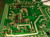
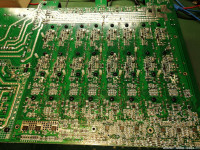
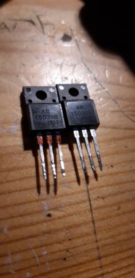
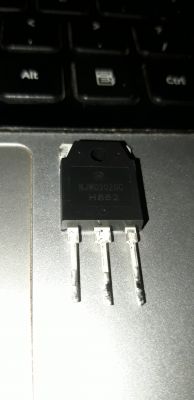
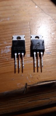
    the entire board has been checked for damaged diodes with the designation EF8 and transistors (because IR2100S, IRGP is known :D ) on the whole board, diodes marked EF8 - damaged 3 pieces (the rest showed only one way about 500 OHM. Power transistors marked: NJW0302GC - damaged pieces 10 (one whole channel, transistors punctured). On the line of damaged power transistors there were also 2 pieces of damaged transistors (mosfets) GP105N15M - damaged 2 pieces. I found another damaged "transistor", I had no pleasure, with the designation KB15038B, which was located next to the damaged power transistors. I have not checked the capacitors yet, only for damage that are visible without measurements :)
    attached photos of the elements
    T.amp TSA 4-1300 Power Amplifier Issue: Not Turning On, Red Diode Flashing, No Visible Damage
    T.amp TSA 4-1300 Power Amplifier Issue: Not Turning On, Red Diode Flashing, No Visible Damage T.amp TSA 4-1300 Power Amplifier Issue: Not Turning On, Red Diode Flashing, No Visible Damage

    Added after 5 [minutes]:

    photos in better quality
  • #30 18276961
    Anonymous
    Level 1  

Topic summary

The T.amp TSA 4-1300 power amplifier exhibits a failure to power on, with a flashing red diode near the capacitors and no visible physical damage. Investigation revealed multiple damaged IRGP4066D IGBT transistors on the primary side inverter, along with damaged power transistors (NJW0302GC), MOSFETs (GP105N15M), rectifier bridges (GBJ3006SF, 2506SF), and driver ICs (IR2110S, SG3525A). The amplifier uses a full-bridge power supply topology operating around 85-100 kHz with multiple symmetrical voltage rails (+/-15V, +/-40V, +/-60V, +/-90V, +/-160V) for preamplifier and power amplifier stages. The power supply design lacks galvanic isolation, current limiting, and effective overload protection, leading to frequent IGBT and associated component failures. SMD components such as EF8 and T4/H5 diodes (likely Schottky and Zener types) near the inverter and driver circuits are critical and often damaged. The triac (BTA41-600B) controlling AC mains to the rectifier bridge is also a common failure point. Repair attempts require replacing IGBTs, driver ICs, rectifiers, and passive components, but without a schematic or service manual, troubleshooting is challenging. Oscilloscope measurements of PWM signals and gate drive waveforms are essential for diagnosing dead time and control issues. Some users suggest replacing the entire power supply with a custom design due to the amplifier’s complex and failure-prone power stage. The amplifier chassis serves as a ground connection, which must be properly connected during bench testing. Auxiliary power supplies (e.g., 2x12V AC transformers) are used to test amplifier channels independently. Despite extensive repairs, issues such as persistent fault LEDs, relay non-activation, and channel-specific transistor failures remain common. The amplifier is considered difficult to service due to integrated power and control boards, lack of documentation, and complex SMD circuitry. The original design is reportedly based on the Chinese Leicozic DP41200 amplifier. Community consensus highlights the need for careful component verification, replacement of damaged SMD diodes and resistors, and cautious startup procedures using current-limited power supplies or light bulbs to prevent repeated damage.
Summary generated by the language model.
ADVERTISEMENT