logo elektroda
logo elektroda
X
logo elektroda

How to connect a digital LED ammeter / voltmeter to the power supply

sofles 40917 20
ADVERTISEMENT
Treść została przetłumaczona polish » english Zobacz oryginalną wersję tematu
  • #1 16631251
    sofles
    Level 8  
    Hi, I have a problem.

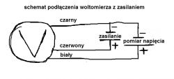
    I converted the old power supply from a computer, I wanted to build a power supply on which I can set the voltage / current, I bought a buck boost converter in one, I connected the 12V power supply to it and connected a digital LED voltmeter ammeter
    3.1.18. Do not send links that will cease to be active after some time. This will make the discussion meaningless.
    [retrofood]

    everything is ok, I can change the voltage by turning the potentiometer, but I can't change the intensity, it shows 0.00A all the time

    I am adding a diagram of how I connected everything and I would be grateful for any help
    How to connect a digital LED ammeter / voltmeter to the power supply
  • ADVERTISEMENT
  • #2 16631258
    edberg
    Level 30  
    To measure it (current value) you have to connect in series, i.e. you cut the cable and connect with one end of the ammeter to one part of the cable and with the other end of the ammeter to the other end of the cut cable. Of course, you must have some load connected because the current flows in a closed circuit ;) .
  • #3 16631264
    Defensore.Puniti
    Level 11  
    Hello,
    sofles wrote:
    Hi, I have a problem.

    I converted an old power supply from a computer, I wanted to build a power supply on which I can set the voltage / current, I bought a buck boost converter in one, I connected the 12V power supply to it and connected a digital LED voltmeter ammeter https://www.aliexpress.com/item/Free-Shipping -DC-100V-10A-Voltmeter-Ammeter-Blue-Red-LED-Amp-Dual-Digital-Volt-Meter-Gauge / 32694138388.html? Spm = a2g0s.9042311.0.0.czsyKa turning the potentiometer change the voltage but I can't change the current, it shows 0.00A all the time

    I am adding a diagram of how I connected everything and I would be grateful for any help
    How to connect a digital LED ammeter / voltmeter to the power supply
    And what kind of 'law' should the ammeter show a value other than zero, since no current flows through it?

    Basics, Fundamentals of Electrical Engineering bow low ... :idea:

    Regards
  • #4 16631270
    sofles
    Level 8  
    Except that when I hook up, for example, a led module to the output, I can normally change the voltage that is sent to the diode, but the current is still 0: /
  • #5 16631290
    Freddy
    Level 43  
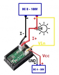
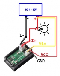
    Is it so hard to check the scheme provided by the sellers?
    How to connect a digital LED ammeter / voltmeter to the power supply How to connect a digital LED ammeter / voltmeter to the power supply
  • #6 16631307
    sofles
    Level 8  
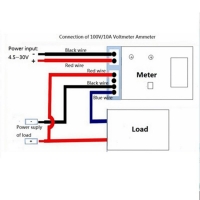
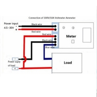
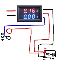
    I have other cables in my own, I do not have yellow, but blue, and I have it plugged in, as recommended by the seller How to connect a digital LED ammeter / voltmeter to the power supply

    unfortunately, it does not do anything, it only measures the voltage
  • ADVERTISEMENT
  • #7 16631319
    Freddy
    Level 43  
    So what if the color is different, but the outputs are the same.
    Why don't you connect as the seller gave you?
  • #8 16631328
    sofles
    Level 8  
    I have it connected as in the diagram above and nothing
  • #9 16631345
    Freddy
    Level 43  
    You're sure of it because I don't.
    Take a picture of your connection, because the scribble drawing is not very reliable.
  • ADVERTISEMENT
  • #10 16631399
    sofles
    Level 8  
    I have it exactly like this How to connect a digital LED ammeter / voltmeter to the power supply
  • ADVERTISEMENT
  • #11 16631415
    Freddy
    Level 43  
    You were supposed to take a picture, not a drawing - don't you know the difference?
  • #12 16633103
    gumisie
    Level 43  
    Freddy wrote:
    Is it so hard to check the scheme provided by the sellers?
    Hello.
    Freddy the connection you suggested is wrong, regardless of the color of the wire (yellow or blue), this wire is the output power supply (-) current consumption measurement is measured at negative voltage (shunt between - black input and - yellow output).
    The connection shown by col. sofles is correct. Reading the current consumption, as someone has already mentioned above, is possible only after connecting a receiver. This module is quite resistant in the case of low currents (fault of the automation).
    Regards.
  • #13 16633133
    Freddy
    Level 43  
    gumisie wrote:
    Freddy, the connection you suggested is wrong
    Since you are sure, I apologize, but it is an image provided by the seller and on the website :) . I still have one.
    How to connect a digital LED ammeter / voltmeter to the power supply
  • #14 16633150
    gumisie
    Level 43  
    Freddy wrote:
    If you're sure then I'm sorry
    Hello.
    100%, I use this type of panels because of the fairly affordable price. I have just unscrewed the power supply to make sure.
    Regards.
  • #15 16633165
    Freddy
    Level 43  
    No problem, I already wrote that sorry . I also use these modules (100V, 10A).
    I will not unscrew my power supply, because it is too much work. :)
  • #16 16633189
    gumisie
    Level 43  
    @ Freddy no one excludes that you are right, the connection issue may arise from the model of this panel. I referred to the YB27VA.
    Regards.
  • #17 16633199
    Freddy
    Level 43  
    My panel is DSN-VC288, but 99% is one and the same.

    The problem is that the author, when asked to remove his layout, inserts a diagram, as if he was ashamed of editing :) .
  • #18 16633278
    gumisie
    Level 43  
    @sofles, Due to the fact that in the network you can actually find various solutions and it is difficult to find out which is the right one and to which panel they can be used, so in my opinion you can check it by measuring the resistance between the blue and black or red wire.
    Regards.
  • #19 17723136
    Cl20
    Level 8  
    edberg wrote:
    To measure it (current value) you have to connect in series, i.e. you cut the cable and connect with one end of the ammeter to one part of the cable and with the other end of the ammeter to the other end of the cut cable. Of course, you must have some load connected because the current flows in a closed circuit ;) .

    And is my reasoning correct when it comes to connecting a voltmeter with a measurement of 0-100 V, which requires a power supply, i.e. one with 3 cables?
    How to connect a digital LED ammeter / voltmeter to the power supply
  • #20 19254449
    Fi_eng
    Level 1  
    Hope you have already solved this but there are many different types of devices. Some have 3 thin wires in one connector: red, black and yellow and two thick wires of red and black. Another type like yours has 3 thick wires in one connector, red, black and blue. That's why in this discussion there is so much confusion. I dropped to this discussion when trying to find proper documentation for these meters like some value of shunt resistor of ampmeter but no success. Just have to calibrate with more accurate device :(

    3 Thin wires + 2 Thick wires
    Red meter operating voltage +
    Black meter operating voltage -
    Yellow voltage sense - high impedance input
    2 Thick wires
    Black ampmeter negative -
    Red ampmeter positive + (from load)

    2 Thin wires + 3 Thick wires
    Red meter operating voltage +
    Black meter operating voltage -
    3 Thick wires
    Black ampmeter negative -
    Blue ampmeter positive + (from load)
    Red voltage sense - high impedance input

    Your connection is correct, so must have problem inside device lice solder break of shunt wire? If you have solved your probem, please reply, it will help me :)
  • #21 19254473
    brofran
    Level 41  
    Cl20 wrote:
    And do I think correctly when it comes to connecting a voltmeter with a measurement of 0-100 V?
    Yes, that's the correct connection.

Topic summary

The discussion revolves around connecting a digital LED ammeter/voltmeter to a modified computer power supply using a buck-boost converter. The user successfully adjusts the voltage but encounters an issue where the ammeter consistently displays 0.00A. Responses emphasize the necessity of connecting the ammeter in series with a load to measure current accurately. Various users suggest checking the wiring connections, as incorrect configurations can lead to measurement failures. The importance of following the correct schematic provided by the seller is highlighted, along with the potential differences in wiring colors and configurations among different models of ammeters. Some users mention specific models and the need for calibration with accurate devices.
Summary generated by the language model.
ADVERTISEMENT