logo elektroda
logo elektroda
X
logo elektroda

The principle of operation of the speed controller of brushless motors for a dro

pablo666007 6642 15
ADVERTISEMENT
Treść została przetłumaczona polish » english Zobacz oryginalną wersję tematu
  • #1 16647752
    pablo666007
    Level 10  
    Hello, I bought a cheap used drone called Intruder Cam, the drive mode has been damaged. I decided to modernize it slowly, wanting to leave the radio and motherboard old and replace the factory engines in it, they were ordinary motors with two cables. I bought 4 brushless motors in this store https://abc-rc.pl/silnik-1400kv-2-3s-180w-abc-power and four regulators https://abc-rc.pl/esc-abc-power-air -30a-bec-2a-simple-regulator And I have no idea how this regulator works, I mean controlling it, i.e. the white cable, I know the rest of the terminals, I don't know what to do with the white cable, that the motor starts to rotate, you need to give voltage, pulse does it have to communicate with any device? The motherboard in it controlled the turnover of the factory engines by simply increasing the voltage

    Best regards and thank you
  • ADVERTISEMENT
  • ADVERTISEMENT
  • #3 16647847
    pablo666007
    Level 10  
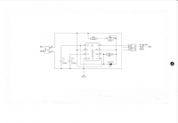
    Oh, or I am starting to more or less understand what's going on, i.e. these regulators are controlled by impulses, I found a diagram on the ne555 system, maybe it would pass the exam. And I have a question whether it is possible to start the engine without building the control system. I probably still have a 555 chip somewhere at home The principle of operation of the speed controller of brushless motors for a dro
  • #5 16648227
    kotbury
    Gantry automation specialist
    Quote:


    W / in the links a bit no hell ...

    Model control signal is not a typical PWM signal - it is a high state repeating every 20 ms and taking values between 1 and 2 ms (description e.g. here: http://forbot.pl/blog/artykuly/elektronika/kurs-elektroniki-ii -6-signal-control-pwm-id9527 - admittedly an example on the servo but the ESC controller works on the same principle only instead of changing the deflection - it changes the engine speed from 0 to max).

    Quote:
    Oh, so I'm starting to more or less understand what's going on, i.e. these regulators are controlled by impulses, I found a diagram on the ne555 system, maybe it would pass the exam

    in the form as in the drawing - certainly not, because it is - a controller for modeling servos / regulators but rather a tester - servo position / motor speed is set by a potentiometer and you need a converter but voltage-controlled.
    Quote:
    And I have a question whether it is possible to start the engine without building the control system

    No. The regulator must receive the signal described above and will come alive.

    Generally, this is first of all without electronic experience (assuming that you will even find a ready converter diagram) - excuse me but the previous questions indicate that you are a bit beginner - you have little chance to assemble and run one.
    Secondly, drones use other solutions (faster - a computer drone reptile with regulators with a much faster protocol - about 10 to 50 times - than ordinary PWM).
    So try to make these dentures: voltage output - brushless regulator you can but how it will work - a lottery ...
    So, as the previous speaker wrote - it would be good to replace the whole set, i.e. the radio - control board - regulators (the engines you bought are suitable)
  • ADVERTISEMENT
  • #6 16648451
    pablo666007
    Level 10  
    I managed to make an engine tester from this diagram, which I included on the Ne555 system, instead of a potentiometer I soldered in front of the system that gave voltage to the factory engine and I managed to get speed control even quite smooth from the drone factory motherboard, you might need to choose the appropriate resistor to control the sensitivity and it should be fine but I can regulate the engine speed with the remote control. Alternatively, you might need to look for some more interesting schematic of the system changing the voltage to pwm
  • #7 16648828
    1 PAWEL
    Level 42  
    And what about the trimmer regulating the rotational speed of engines (there are no ideal parameters for each engine and regulator) to correct the position.

    The principle of operation of the speed controller of brushless motors for a dro
  • ADVERTISEMENT
  • #8 16648860
    pablo666007
    Level 10  
    Self-adjusting speed for position correction also works. Only this engine is a little more sensitive I will play with the selection of resistors in this system on ne555 but generally works smooth speed control from the remote control now I have to make a new frame because it bends you can see that the engine is stronger and etch the plates under the systems on ne555 and assemble the whole :) I am curious myself how it will fly, it will succeed, it is worth trying, if not I will change electronics, but these engines have a completely different working culture compared to the old ones on gears, so maybe it will be better :) I am happy that it works and what we will see next :)
  • #9 16650426
    KJ
    Level 31  
    Maybe it will be easier to buy a finished carbon fiber frame? In my opinion, converting a brush drone into brushless motors is meaningless as functional and economical. It is cheaper to buy a flight controller that directly supports BLDC motors (directly in the sense of PWM outputs for ESCs). It also depends on what this drone is to be used for - as for fun and fun with flying I suggest building based on the F3 / F4 controller supporting betaflight / cleanfligt as for learning how to fly it is best to buy a toy from china - e.g. Eachine H8S / H8S 3D - cost none and the fun of flying a lot and flight physics similar to larger drones. A drone for filming is another pair of wellies ;) It would be worth having a gimbal, gps, live view, longer flight time, etc. I wonder if at present it makes economic sense to build such a drone yourself - it won't come out much cheaper than a phantom.
  • #10 16651181
    pablo666007
    Level 10  
    It would be easier to buy everything ready but it is about satisfaction with the work done. Now I am at the stage of making arms, I already have two. The whole frame will be aluminum, there are two more arms and the means connecting them, and design and etch the general plate to distribute the voltage to the motors and together with the ne555 systems changing the voltage control to a pwm signal to regulators. If the idea with electronics does not work in the sense that there will be a problem with controlling the drone in the air, it is difficult to buy a new one and the frame with engines will be ready.
  • #11 16651641
    wada

    VIP Meritorious for electroda.pl
    Most often the PWM signal comes out of the receiver, and this goes for a simple RC filter and brush motor controllers.
    It is better to look for the original PWM signal and not play 555. And completely get rid of the brush power amplifiers - they needlessly consume a lot of valuable current.
  • #12 16651660
    pablo666007
    Level 10  
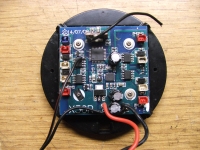
    All in all, right with looking for the original pwm signal I will look more closely at all the electronics. But probably old power amplifiers not loaded with engines do not consume a lot of power at least I think so :) Desolder not a hassle as you will need :) I put a photo of the electronics that sat in it, it may be useful for advice.
  • #13 16651675
    PiotrPitucha
    Level 34  
    Hello
    defect , PPM is usually used in modeling receivers, not PWM.
    In addition, pins with a width of about 200us come out of the receiver as such and only after the channel decoder are they "virulent" for servos and motors.
    As for motor controllers, you are also wrong, there are no filters and amplifiers there, the regulators replace PPM for PWM for motors and are made on microcontrollers.
    From the regulation side, the brushless and brush motors are controlled identically.
    If you don't believe it, count how much power your "amplifiers" would have to release if you controlled it analogously, 4 engines, some 10A-30A in bigger models and even a radiator for cooling ...
    Regards
  • #14 16651680
    pablo666007
    Level 10  
    Photo because I forgot to add, this is how all the drone's electronics look like :) there are no miracles but as seen :) The principle of operation of the speed controller of brushless motors for a dro The soldered cable "before" the 8-leg system is my signal that controls the system on ne555 and works amazingly :) but maybe someone has a better idea on how to improve it
  • #15 16652193
    wada

    VIP Meritorious for electroda.pl
    The assuming subject did not provide any details of the original, and no pictures.
    And in short, I wrote that he would look for the original PWM, and not create it again, with additional power consumers.
    the assuming topic wrote that the output to the motor has a direct voltage, i.e. there is a RC filter - maybe it is just a capacitor at the output of the amplifiers, protecting against sparking brushes.

    Without knowing the details, you can only write vaguely.

    And as for power amplifiers, probably everyone knows how they work in this type of engine controls and you do not need to write about them.

    PiotrPitucha wrote:
    From the regulation side, the brushless and brush motors are controlled identically.

    And that's what I meant when writing the previous post in short.
  • #16 16653907
    PiotrPitucha
    Level 34  
    Hello
    defect , it may be time to enter "brushless control engine" in Google instead of writing guesses and earning points on your account ....
    If you want to power a brushless DC motor then congratulations on your humor.
    Generally, it is not profitable to make controllers for both brushless and brush motors, the sum of the prices of parts is greater than the finished product, while at the control level we have identical signals which relieves us from agonizing or something fits the set.
    The driver is selected for the motor for a specific current and voltage, the rest will match.
    Regards

Topic summary

The discussion revolves around the operation of speed controllers for brushless motors in a drone, specifically the Intruder Cam model. The user seeks to understand how to control the newly purchased brushless motors and electronic speed controllers (ESCs) after replacing the original brushed motors. Key points include the necessity of a PWM (Pulse Width Modulation) signal for controlling the ESCs, which can be generated using a NE555 timer circuit. Participants emphasize the importance of using a proper receiver and transmitter setup to send the PWM signal to the ESCs. There are suggestions to avoid using outdated power amplifiers and to focus on finding the original PWM signal from the drone's electronics. The user successfully created a motor tester using the NE555 circuit, allowing for speed control via remote control. The conversation also touches on the feasibility of converting a brushed drone to brushless motors and the potential need for a new flight controller that directly supports brushless motors.
Summary generated by the language model.
ADVERTISEMENT