logo elektroda
logo elektroda
X
logo elektroda

Arduino EC Motor Control: BLDC with 0-10V PWM, Transistor BD139 & Regulator R-1/010 Integration

1wheler 13608 19
ADVERTISEMENT
Treść została przetłumaczona polish » english Zobacz oryginalną wersję tematu
  • #1 16351606
    1wheler
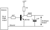
    Level 10  
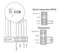
    I have an EC motor in the recuperator with 0-10V control. When the 10V jumper is closed with the 0-10V jumper, the engine works at maximum speed.

    Can you control this voltage with arduino via PWM?
    Is it enough to connect a transistor, e.g. BD139, to the PWM pin on the arduino?

    I enclose a picture of how regular adjustment looks like with the Regulator R-1/010.
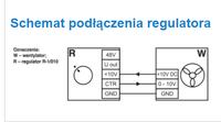
    Arduino EC Motor Control: BLDC with 0-10V PWM, Transistor BD139 & Regulator R-1/010 Integration
    Do you have a problem with Arduino? Ask question. Visit our forum Arduino.
  • ADVERTISEMENT
  • #2 16352363
    tmf
    VIP Meritorious for electroda.pl
    You can ordinary PWM + transistor to make 0-10V and RC filter on the output.
  • #3 16360248
    1wheler
    Level 10  
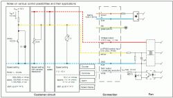
    Here I have the exact EC engine control scheme.
    and all in all i have no idea how to connect this to the transistor. PWM from Arduino on Base ?? what about the rest??
    Arduino EC Motor Control: BLDC with 0-10V PWM, Transistor BD139 & Regulator R-1/010 Integration

    edit.

    I made the layout according to the attached diagram, it works. only has a disadvantage, when PWM is 0V, then output voltage is 10V and when PWM is 5V, output voltage is 0.2V.
    Arduino EC Motor Control: BLDC with 0-10V PWM, Transistor BD139 & Regulator R-1/010 Integration
    Is it possible to build a system to increase Vwy as PWM increases.

    Because in this option, if I turn off the arduino, the fan will run at maximum speed.
  • #4 16360658
    dondu
    Moderator on vacation ...
    Change the PWM signal to the opposite with the program (see microcontroller documentation - search: inverting-mode).
  • ADVERTISEMENT
  • #5 16361271
    1wheler
    Level 10  
    inverting-mode will only change for me from the side of the program, physically it will be the same.
    at 0.2V base U; Uwy will be max

    and I mean physical dependence, U control increases (base, PWM there) and Uwy increases simultaneously.

    This can use LM538 ??
  • #6 16362245
    dondu
    Moderator on vacation ...
    Think about what you write.
    The transistor introduces signal inversion. It is enough to negate the PWM signal fed to the base of the transistor.
    This is done by programming the PWM signal type in "inverting mode".

    What would the LM538 do?
  • ADVERTISEMENT
  • #7 16362481
    1wheler
    Level 10  
    I thought about it and supported what I wrote.
    What happens if I turn off the arduino or disconnect the PWM ????
    Uwy will not be 0V, only 10V.
  • ADVERTISEMENT
  • #8 16362516
    dondu
    Moderator on vacation ...
    1wheler wrote:
    what happens if I turn off the arduino, ...

    You haven't written about it before.

    1wheler wrote:
    ... or disconnect PWM ????

    What does it mean to disconnect PWM? Where How? Physically or programmatically?
  • #9 16363232
    tmf
    VIP Meritorious for electroda.pl
    1wheler wrote:
    I thought about it and supported what I wrote.
    What happens if I turn off the arduino or disconnect the PWM ????
    Uwy will not be 0V, only 10V.


    Then add an additional negation. By the way, after turning on ATMega has all the pins as input, so just add a resistor polarizing the transistor and after the problem.
  • #10 16766444
    1wheler
    Level 10  
    I was building the layout from post # 3
    at first I did tests without RC, but without connecting the EC motor
    now I have attached the RC filter, and in the idle state of operation, the R680 heats up a lot.
    I also have some concerns whether such a filter will quite effectively smooth the sine wave (I do not have an oscilloscope, so I will not check)
    maybe some other sure way to drive an EC motor through arduino. (the fan alone cost PLN 950) so I don't want to release it.
  • #11 16920545
    raven5
    Level 9  
    1wheler wrote:
    I was building the layout from post # 3
    at first I did tests without RC, but without connecting the EC motor
    now I have attached the RC filter, and in the idle state of operation, the R680 heats up a lot.
    I also have some concerns whether such a filter will quite effectively smooth the sine wave (I do not have an oscilloscope, so I will not check)
    maybe some other sure way to drive an EC motor through arduino. (the fan alone cost PLN 950) so I don't want to release it.

    And who told you that Harmann EC fans are controlled by a pulse from the pwm comparator? :) , but there is clearly shown in the diagram and probably in the manual is also described that the change in speed occurs by adjusting the analog voltage from 0v to 10v.
    I have already worked on this topic some time ago it is probably just ebm papst blowers have both pwm dc and ec control.
    For this harmony you need a regular potentiometer and if you want to have a digital control then you need to look for some digital potentiometer.
  • #12 16927070
    1wheler
    Level 10  
    ok, the topic is over.
    I know that the EC fan is not controlled by pwm, that's why the RC filter is installed.
    I made the whole system as in the above scheme, instead of 680R I gave a 3k3 resistor and a BC337 transistor.
    The whole is controlled with arduiono mini pro.
    Speed control is smooth.
    The goal has been achieved.
    It is a control of the recuperator which I built on two EC 150/650 fans and a countercurrent exchanger.
  • #13 16971495
    cezarek2
    Level 2  
    Hello gentlemen, I have a problem and I ask for advice.
    I have ebm papst ec fans controlled by pwm and a 0-10v signal driver from tech st-340 - how to reconcile it?
  • #14 16971513
    es2
    Level 16  
    cezarek2 wrote:
    pwm controlled and 0-10v signal controlling driver

    Use a second PWM to generate 0..5V and operational amplifier to multiply the voltage by 2. Naturally, pay attention to the amplifier's input and output voltage range.
  • #15 16971612
    cezarek2
    Level 2  
    could you give exactly what to buy and how to connect it?
  • #16 16971665
    es2
    Level 16  
    cezarek2 wrote:
    could you give exactly what to buy and how to connect it?

    Naturally. It will take me an hour or two. How is the hourly rate for electronics now?
  • #17 16972220
    Anonymous
    Level 1  
  • #18 16972477
    es2
    Level 16  
    emarcus wrote:
    There is no need to use an operational amplifier to get a PWM signal with an amplitude of 10V ... (this is probably the requirements of this motor (?). Unnecessary complication of the system.

    This should be a voltage in the range of 0..10V and not a PWM signal with an amplitude of 10V.
    Of course, you can "sculpt" on transistors, give OC output, pull up to +10, then RC filter and buffer on the transistor. I prefer to give an operational amplifier.
  • #19 16972978
    Anonymous
    Level 1  
  • #20 16973008
    es2
    Level 16  
    emarcus wrote:
    You use one method (0 to 10 V analog signal) or PWM (10 V) instead of both.

    No matter what method you use, you need to give 0..10V:
    Arduino EC Motor Control: BLDC with 0-10V PWM, Transistor BD139 & Regulator R-1/010 Integration
    Whether in the form of pulses or direct voltage.
    The R-1/010 regulator is a potentiometer for me (130 PLN).

Topic summary

The discussion revolves around controlling an EC motor with a 0-10V input using an Arduino and PWM signal. Users explore the integration of a BD139 transistor and an R-1/010 regulator to achieve the desired voltage control. Initial attempts with PWM resulted in inverted output voltages, prompting suggestions to negate the PWM signal in software or add additional circuitry to ensure proper voltage scaling. Concerns about the motor running at maximum speed when the Arduino is off led to discussions about using resistors and operational amplifiers to stabilize the output. Ultimately, a successful configuration was achieved using a BC337 transistor and an RC filter, allowing for smooth speed control of the EC motor.
Summary generated by the language model.
ADVERTISEMENT