logo elektroda
logo elektroda
X
logo elektroda

Makita DC18RC Charger Repair: Identify IC1 (1D12308), R91 Resistor & D14 Diode Replacement

andsab 21999 16
ADVERTISEMENT
Treść została przetłumaczona polish » english Zobacz oryginalną wersję tematu
  • #1 16695245
    andsab
    Level 15  
    Hello. I have a damaged charger as in the topic. The R91 resistor and the D14 diode were burned out. After replacing them, the charger still does not work. I think that IC1 is still to be replaced. Unfortunately, I do not know what layout it is, it writes 1D12308 on it. By typing it in google nothing pops up. Please let me know what layout it is.
  • ADVERTISEMENT
  • #2 16695251
    miecho18
    IT specialist
    What is the housing of this chip?
  • #3 16695259
    andsab
    Level 15  
    S08 housing.
  • #4 18195727
    Mario 814
    Level 11  
    I am just repairing such a charger. In addition to the R91 2R4, D14 zenerka 30V, I also had the Q3 KF2N60 transistor and the R29 2R2 resistor. So far I have ordered parts, let's see if it helps. IC1 is from the main converter and damaged components belong to the auxiliary converter.
  • ADVERTISEMENT
  • #5 18195871
    Anonymous
    Level 1  
  • #6 18196069
    gumisie
    Level 43  
    @andsab take some clear photos and post them here on the forum.
    Maybe it will be easier for you to help.
  • ADVERTISEMENT
  • #7 18217570
    Mario 814
    Level 11  
    After replacing the damaged elements, the converter started, but instead of the expected 12V, I got only 1.95V at the output. After a long fight, it turned out that the culprit is the SMD C17 6.8nF capacitor. After replacement, 12.4V appeared at the inverter's output, the charger is working properly :D

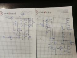
    PS. If I need someone, I have a handwritten diagram of this converter.
  • ADVERTISEMENT
  • #8 18219683
    gumisie
    Level 43  
    Mario 814 wrote:
    PS. If I need someone, I have a handwritten diagram of this converter.
    So before you close a topic, it would be advisable to include it here.

    Regards.
  • #9 18319012
    Mario 814
    Level 11  
    I present a hand-drawn diagram of an auxiliary converter. Makita DC18RC Charger Repair: Identify IC1 (1D12308), R91 Resistor & D14 Diode Replacement
  • #10 18502803
    magnum1978
    Level 1  
    Hello, I have a Makita double charger has stopped working, there are no damaged elements, i.e. the theoretical plate looks the same as in a single 18, maybe someone will suggest something
  • #11 18609376
    Mircio82
    Level 2  
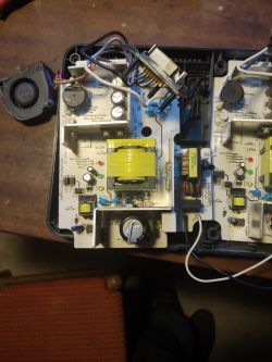
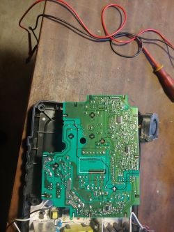
    Hello, I also have a Makita DC 18RC S double charger. One side is working properly, ie it is charging the battery, while the other side is not charging. After unscrewing the charger, I found that the F101 T4AH AC 250V fuse was blown. After inserting a new one, this one is also burned, which means there must be a short circuit somewhere. I will put a few photos of my charger here, maybe someone will say visually why it is not charging.
    Makita DC18RC Charger Repair: Identify IC1 (1D12308), R91 Resistor & D14 Diode Replacement Makita DC18RC Charger Repair: Identify IC1 (1D12308), R91 Resistor & D14 Diode Replacement
  • #12 18610920
    Mario 814
    Level 11  
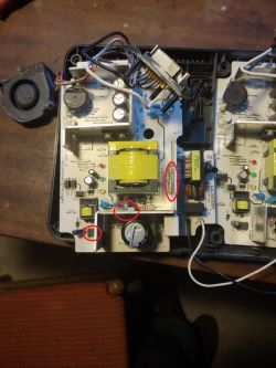
    Mircio82 you should check the rectifier bridge (diodes), the Mos-fet transistor and the auxiliary converter circuit for a drain-source short circuit. Items marked in the photo.
    magnum1978 both sides not working? Fuse as for Mircio82 working? High voltage after bridge rectifier present? Makita DC18RC Charger Repair: Identify IC1 (1D12308), R91 Resistor & D14 Diode Replacement
  • #13 18618330
    Mircio82
    Level 2  
    Mario 814 wrote:
    Mircio82 you should check the rectifier bridge (diodes), the Mos-fet transistor and the auxiliary converter circuit for a drain-source short circuit. Items marked in the photo.
    Hello Mario814, thanks for the advice, what I can check only in the problem that I do not know how to do it, I only have the simplest electrical meter at home. It's nice if you write step by step how to check the elements you indicated. Regards
  • #14 18620824
    Mircio82
    Level 2  
    Mario, I checked the transistor and bridge today, but I don't know how to check the third element. There is little information on the Internet on how to do this. Maybe it will help, but I did not write that the fuse burns without the battery attached.
  • #15 18621772
    Mario 814
    Level 11  
    Makita DC18RC Charger Repair: Identify IC1 (1D12308), R91 Resistor & D14 Diode Replacement

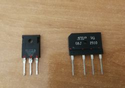
    Hope you checked these items well. The Mosfet bridge and transistor is best checked by setting the meter to measure the diode. In the bridge we connect the positive end of the meter to the "-" bridge, and the negative end to one and then the other "~" terminal. The output should be about 0.45 - 0.6 V. Then the meter minus to the "+" bridge, and the meter plus to one and then to the other "~" terminal of the bridge. It should work out similarly. Also check that there is no short circuit between the "+" and "-" jumper and the "~" and "~" terminals. The transistor is checked for a short circuit between the drain and the source. Connect the meter plus to the "S" source, and the meter minus to the "D" drain (at the Mosfet transistor with N channel). The output should be about 0.3 - 0.5 V. To be sure, you can check the transistor's Datasheet to see if it has a diode between the drain and the source. There should definitely not be a short circuit there. As for the third element, find a Datasheet for it and identify which pins have the drain and the source of the transistor keying the converter and measure as above. Picture with an example bridge and Mosfet transistor. Good luck.
  • #16 18622337
    Anonymous
    Level 1  
  • #17 18622391
    gumisie
    Level 43  
    Gentlemen.
    The author of the topic, founded: 12 Sep 2017 15:24 and is still "silent".
    Are we not violating the electrode regulations? :cry:

    Regards.

Topic summary

The discussion revolves around the repair of a Makita DC18RC charger, specifically addressing the replacement of damaged components including the R91 resistor, D14 diode, and the IC1 integrated circuit marked as 1D12308. Users share their experiences with similar repairs, noting that additional components such as the Q3 transistor and C17 capacitor may also be faulty. Suggestions include checking all semiconductors and components systematically due to the prevalence of low-quality parts in chargers. A hand-drawn diagram of the auxiliary converter is provided for reference, and troubleshooting advice is shared, including methods for diagnosing short circuits and testing components with a multimeter.
Summary generated by the language model.
ADVERTISEMENT