logo elektroda
logo elektroda
X
logo elektroda

Bosch 18V-40 Charger - Identifying Damaged PCB Components, Transistor W1A, Resistor Values

carl0s 13821 36
ADVERTISEMENT
Treść została przetłumaczona polish » english Zobacz oryginalną wersję tematu
  • #1 19488379
    carl0s
    Level 2  
    hello,

    I have a charger as in the subject.
    The charger, according to the user's description, "breathed fire" during normal operation and has not turned on since.

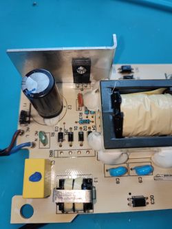
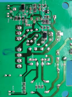
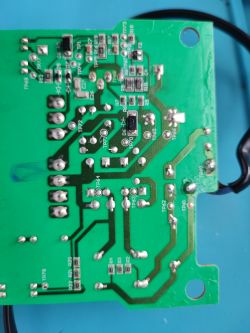
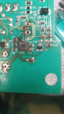
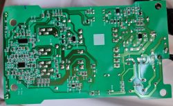
    After opening the housing, I located the place of damage, actually blackened both the PCB and the housing from the inside.
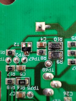
    Bosch 18V-40 Charger - Identifying Damaged PCB Components, Transistor W1A, Resistor Values Bosch 18V-40 Charger - Identifying Damaged PCB Components, Transistor W1A, Resistor Values

    And now a question for you - does anyone know the values of the resistors and what kind of transistor it will be?
    From another thread about 1880 I only learned that the transistor may be W1A, but I am not sure.
    will you help?
  • ADVERTISEMENT
  • #2 19488406
    jaeger
    Level 13  
    1. There is no full information, photo of the rating plate/label...... I understand that this is a Bosch GAL 18V-40 charger?

    2. Take more macro photos so that you can see what, for example, the driver is. Also check the key (power transistor) and if it is burned, or rather it just happened, desolder it and also take a clear photo of it.

    3. Also check if there are fuse, rectifier, starting thermistor, electrolytic capacitors.

    4. Make the first start-up after repair by powering the charger in series through a 25-40W tungsten bulb. If the bulb remains bright without the battery, the repair has failed.
  • #3 19488790
    carl0s
    Level 2  
    1. Yes, it is GAL18v-40.
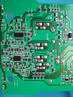
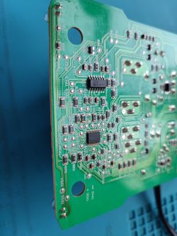
    2. Photos - I can take a microscopic photo of each fragment, however, I looked at the whole thing from both sides and the visible damage is only those from the first post and the 2.5a fuse, which I did not mention because I considered it too obvious.
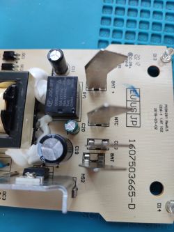
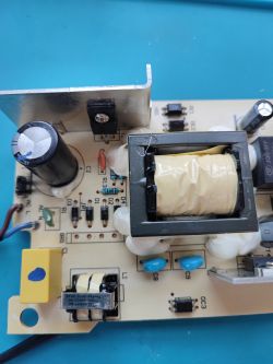
    Bosch 18V-40 Charger - Identifying Damaged PCB Components, Transistor W1A, Resistor Values Bosch 18V-40 Charger - Identifying Damaged PCB Components, Transistor W1A, Resistor Values Bosch 18V-40 Charger - Identifying Damaged PCB Components, Transistor W1A, Resistor Values Bosch 18V-40 Charger - Identifying Damaged PCB Components, Transistor W1A, Resistor Values Bosch 18V-40 Charger - Identifying Damaged PCB Components, Transistor W1A, Resistor Values Bosch 18V-40 Charger - Identifying Damaged PCB Components, Transistor W1A, Resistor Values Bosch 18V-40 Charger - Identifying Damaged PCB Components, Transistor W1A, Resistor Values Bosch 18V-40 Charger - Identifying Damaged PCB Components, Transistor W1A, Resistor Values

    Unfortunately, none of my friends have this charger model to check the markings of damaged elements.
    I would replace the power transistor right away, but Google does not provide any replacement.
  • ADVERTISEMENT
  • #5 19489287
    jaeger
    Level 13  
    Well, you see, and there was no plate to know what power this charger consumes.....
    But I found nothing that it is 95W, which at 230VAC mains voltage should give slightly less than 500mA effective current.
    And now, assuming that it is a flyback power supply, i.e. the most likely type, it concludes a bit on the nose that the parallel connection of R9 and R10 should be about 100mR, i.e. R9 = R10 + 200mR. But I don't know and it could be different.

    You would have to experiment with different resistors, e.g. from 1R and then down and measure the drain currents and the charging current. Check if the transformer is not saturating (oscilloscope) and accordingly correct down the transistor current by increasing the resistors in its source (R9+R10).

    Unfortunately, I do not see what the charger controller is, but it is probably a programmed uC, so you have to follow the above.

    Selection of the transistor ... and here I am wondering about the drain current, because why 8A with a power of about 100W? Maybe 2A would be enough here?
    The breakdown voltage is worse, because perhaps 600V is not enough here.

    Well, maybe "on the cheap" STP3NK90ZFP. 5x higher resistance, i.e. 0.9R vs 4.8R at an average current of 500mA, will not cause significant power losses here.

    Check out T2 again. I don't like his face
  • #6 20341969
    pegas6688
    Level 1  
    I have a similar problem.
    And here is my question regarding the burnt T2, R9 and R10 elements. Is it possible to select and start the charger? If so, please provide them.

    Bosch 18V-40 Charger - Identifying Damaged PCB Components, Transistor W1A, Resistor Values
  • #7 20345279
    jaeger
    Level 13  
    It seems that there are only 2 transistors on the primary side, in which case you can use e.g. BC848 or faster MMBT3904 instead of T2. But first check if the PIN'out matches because I have the impression that in this transistor the base is in the middle.

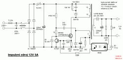
    Most likely, on the primary side, the power supply will resemble this arrangement:

    Bosch 18V-40 Charger - Identifying Damaged PCB Components, Transistor W1A, Resistor Values

    I do not know what value the resistors R9 and R10 have, but you can risk, for example, 1R. The simulator gave me a parallel connection resistance of about 400mR, i.e. R9=R10=800mR.
  • #8 20391226
    TUNOR
    Level 10  
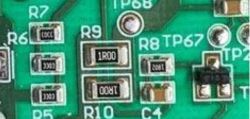
    Generally, R9 and R10 are two of the same 1R00 1/4W resistor (size 1206). As for the T2 transistor, I'm not 100% sure, but it's 90% 2n3904
    Bosch 18V-40 Charger - Identifying Damaged PCB Components, Transistor W1A, Resistor Values

    I am struggling with the repair of this charger myself, after replacing the transistor T1, T2, T4, diodes from the bridge, resistors R9 and R10, the bulb still does not go out.
    The charger does not have a classic Schottky diode at the transformer output, but is based on the AT10700P MOSFET (T4) transistor. I did not find any other burns or low circuit resistance on the board. Because of the 40W bulb, I also did not find places that would cause heating (unfortunately, the test was done with IPA, because there is no thermovision). This pi ... varnish does not make it easier to diagnose either.
    On the positive side, applying power to C11 caused the green diode D13 to light up, so there is a shadow of hope that the ICs survived.
  • #9 20396426
    jaeger
    Level 13  
    The varnish can be washed off with a universal solvent. By the way, inscriptions from electrolytes will come off :-)
  • #10 20748524
    furtek
    Level 14  

    >>20391226
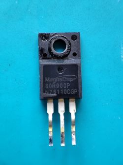
    Did you manage to repair this charger? After the diagnosis of my GAL 18v-40 charger, the t1 80r900p bridge was damaged, the resistors R9 and R10, the t2 transistor was also damaged, it looks like the T4 transistor survived, it is not shorted. What did you replace transistor t2? And did you manage to run it?
  • #11 20794188
    gontarzartur
    Level 5  
    Hello.
    I also struggled with this charger. After replacing T2 marked W04 and R9 and R10 with 1R00 and the 80R900P transistor, the charger came to life and works. Regards.
  • #12 20871486
    cristiyantoro1
    Level 1  

    I had a similar problem where resistors R9+R10 and transistor T2 .. I suspect it was caused by a short circuit from the T1 80R900Z MOSFET so there was a voltage spike
  • #13 20940972
    StuBoy
    Level 1  

    I am just looking at the same power supply with what looks like the same fault. Mine also has secondary issues though. I will let you know how I get on after replacing the R9, R10, and associated components.
    Cheers,
    Stu
  • ADVERTISEMENT
  • #14 21004477
    gracus7
    Level 26  
    Hello, I have just repaired my charger, just like yours
    80R900P
    T2 =W1A, = PMBT3904
    R9 and R10 = 1ohm,
    gretz bridge
    8S150L thermistor
    F1, 2.5A
    but on the secondary side it failed
    electrolyte,
    2 pcs R55 and R54 330 Ohm
    IATPN = MP6907GJ-Z which had a short circuit.
    After replacing the above elements, the charger came back to life
    As a preventive measure, I added a larger heat sink to the mosfet
  • #15 21042988
    matanda
    Level 1  

    Can anyone advise on a way to convert this tool to use 240VAC? I have a US version (120V) similar to the original poster's with some slight differences.
    1. It has a GBU808 on BR1 instead of the diodes, D1-D4.
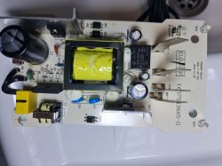
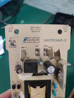
    2. JP1 is installed on mine, as opposed to what was originally posted

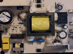
    Circuit board with electronic components, including a transformer, capacitors, and a GBU808 bridge rectifier.

    There are similar guides on the Internet for other brands of chargers but not for this particular one. Usually the JP1 would be reduced and a bigger varistor installed.

    Hopefully the additional pictures help in understanding
    Close-up view of a circuit board interior with various electronic components.
    Charger circuit with electronic components on a printed circuit board.
  • ADVERTISEMENT
  • #16 21210598
    yaro77
    Level 13  
    Hello
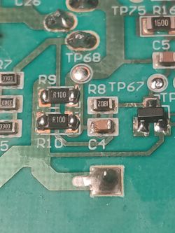
    I have a faulty 18V-40 charger, I have replaced the faulty components and after connecting through the bulb, the bulb flashed slightly , upon inspection you can see a eaten C4 capacitor.
    What should be its value? Close-up of a damaged circuit board with the capacitor C4 visible. .
  • #17 21211886
    gracus7
    Level 26  
    This capacitor is 1uF and I also replaced it at my place
  • #18 21211919
    yaro77
    Level 13  
    1uF just for how many volts ????
  • #19 21211928
    gracus7
    Level 26  
    This capacitor is not an electrolyte. Pull a similar one from some demob board.
  • #20 21211941
    yaro77
    Level 13  
    Super only these SMD capacitors were for 25V and 100V , the ones for higher voltages rather have larger dimensions.
    I know they are not electrolytes.
  • #21 21211946
    gracus7
    Level 26  
    So you have answered yourself. Take the same dimensionally and it will be ok.
  • #22 21263861
    holymakrels
    Level 1  
    Hi All could someone help me I have also this Bosh charger but I get on the battery poles not DC but AC which component could be wrong I have checked diodes and they are ok what could be wrong? thank you for your help.
  • #23 21319362
    pedrohen1957
    Level 1  
    Can someone tell me what CI AITPP means, I couldn't find it in the data sheet. If you can help me, I would appreciate it.
  • #24 21319915
    gracus7
    Level 26  
    This is the code for this chip MP6907GJ-Z
    https://eu.mouser.com/ProductDetail/Monolithi...J37_wxqlT5Xm54TRJ9_0QIRFWgP0wB68CyVrAOZ_lGmYP

    https://pl.aliexpress.com/item/4001245012031.html?gatewayAdapt=glo2pol

    Added after 9 [minutes]:

    >>21263861 maybe you have a short between the primary and secondary of the power supply, a shorted transformer, or the measuring device is showing something wrong. If the diodes are OK, then there must be a short-circuit behind the diodes and the optocoupler?
  • #25 21352076
    yaro77
    Level 13  
    Hello, I am once again returning to repair this charger. I have replaced the faulty components but it still does not start, when I apply voltage to capacitor C19 the green LED lights up.
    When I supply power normally from the mains there is the correct voltage over 310V on the trafo.
    No voltage on the secondary side, i.e. the Mosfet does not key.
    One optocoupler is fed from the hot side with AC voltage, is this how it will work?
    Where to look for the fault?
    IATPN prophylactically also replaced.
  • #26 21355628
    gracus7
    Level 26  
    What have you listed, one at a time?
  • #27 21356018
    yaro77
    Level 13  
    Hello, I have replaced:
    80R900P
    T2-W1A
    R9, R10
    F1
    No hot side short circuit.
    Also prophylactically IATPN
  • #28 21356135
    gracus7
    Level 26  
    And the 2 pcs of R55 and R54 330 Ohm do you have whole? electrolyte next to it too? maybe check the transformer keying transistor. just because it's new doesn't mean it's working.
  • #29 21356879
    yaro77
    Level 13  
    Resistors working, electrolytes checked, Mosfet conducts as it should i.e. source - drain and after charging source - gate.
    I noticed that after applying and de-energising the voltage on the primary side and capacitor C2 there is still voltage.
    That is, the Mosfet is not keying and energy is stored only on the primary side of the inverter.
    The optocoupler OC3 tells the cold side that the high voltage is on the hot side OC1 controls the Mosfet to turn off and release energy from the inverter.
    What is the role of OC2?
    Am I seeing correctly that the diode in OC3 is AC powered?
    Please correct me if I misunderstand something and have written incorrectly.
    I am not an electronics engineer, trying to fix this myself, is this an extended Flyback inverter ?
  • #30 21358116
    gracus7
    Level 26  
    You don't mention anything about C4 which you had a problem with. soldered 1uF in?

Topic summary

The discussion revolves around the Bosch GAL 18V-40 charger, which experienced a failure characterized by internal damage and a "fire" incident during operation. Users shared their experiences diagnosing and repairing the charger, identifying damaged components such as the power transistor (W1A or PMBT3904), resistors (R9 and R10, typically 1Ω), and the bridge rectifier (80R900P). Suggestions included taking macro photos for better identification of components, using a bulb for initial power-up tests, and experimenting with resistor values to ensure proper functionality. Some users successfully repaired their chargers by replacing the damaged parts, while others sought advice on specific components and their values. Additionally, there were inquiries about converting the charger for different voltage inputs and addressing issues with AC output on battery poles.
Summary generated by the language model.
ADVERTISEMENT