FAQ
TL;DR: Build 10+ band analyzers with band‑pass filters, log‑scale drivers, and multiplexing; “I made my first analyzer on 20 UL1980 chips.” [Elektroda, zybex, post #19450864]
Why it matters: This FAQ helps DIYers choose between LM391x chains, microcontrollers, or ready kits to get dense 40‑LED columns with sane cost and power.
- Typical kit budget: about $35 for a ready spectrum‑analyzer board. [Elektroda, beatom, post #16734632]
- Use logarithmic (dB) scaling for music/speech dynamics; linear scales misread peaks. [Elektroda, Hektar Zahler, post #16735048]
- Multiplexing lets one VU/driver handle many columns, reducing parts and heat. [Elektroda, Hektar Zahler, post #16735048]
- Analog filter banks need individual tuning; large builds raise cost fastest. [Elektroda, kotuniunia, post #16734788]
- Legacy builds: 10 channels per stereo with ~220 LEDs is common. [Elektroda, zybex, post #19450864]
Quick Facts
- Typical kit budget: about $35 for a ready spectrum‑analyzer board. [Elektroda, beatom, post #16734632]
- Use logarithmic (dB) scaling for music/speech dynamics; linear scales misread peaks. [Elektroda, Hektar Zahler, post #16735048]
- Multiplexing lets one VU/driver handle many columns, reducing parts and heat. [Elektroda, Hektar Zahler, post #16735048]
- Analog filter banks need individual tuning; large builds raise cost fastest. [Elektroda, kotuniunia, post #16734788]
- Legacy builds: 10 channels per stereo with ~220 LEDs is common. [Elektroda, zybex, post #19450864]
How do I build a 10‑band acoustic spectrum analyzer like in the video?
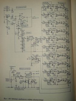
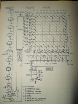
Split audio with 10 band‑pass filters, rectify each band, and feed a logarithmic bar‑graph driver. Use multiplexing to cut parts and heat while keeping 40‑LED columns bright. “The appendix describes the multiplexed analyzer,” which explains why this approach scales well. [Elektroda, Hektar Zahler, post #16735048]
Can I start with 10 lines and expand to more later?
Yes. Design the front‑end and driver for multiplexing and add more filter channels in groups. Expansion mainly means adding filters and routing those outputs through the existing multiplexer to the display. Keep the same log‑scale driver settings. [Elektroda, Hektar Zahler, post #16735048]
Is there a cheaper option than chaining LM3915/LM3916 for many LEDs?
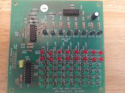
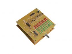
Buy an off‑the‑shelf kit. Builders report complete spectrum‑analyzer kits from China around $35, which is often cheaper than many discrete LM391x chips and PCBs. [Elektroda, beatom, post #16734632]
Do I really need logarithmic scaling for audio levels?
Yes. Music and speech have high dynamic range measured in dB. A linear scale under‑represents low‑level content and clips peaks. A log‑scale driver (e.g., LM3916) matches how we perceive loudness and keeps columns informative. [Elektroda, Hektar Zahler, post #16735048]
What does “multiplexed analyzer” mean here?
The display is time‑shared. A multiplexer quickly scans each band’s level into one driver, so you need fewer driver chips. You still use separate filters per band; only the display path is multiplexed, cutting cost and heat. [Elektroda, Hektar Zahler, post #16735048]
Is a non‑multiplexed display a bad idea?
It works, but wastes power and parts because all LEDs and drivers are active continuously. As one expert noted, the “display is not multiplexed,” which is wasteful with large arrays. [Elektroda, Hektar Zahler, post #16734611]
How do I make the band‑pass filters, and what’s the catch?
Build a filter per band (e.g., op‑amp active filters). The catch: you must tune each one to its center frequency. On big builds, this tuning effort and cost dominate the project. [Elektroda, kotuniunia, post #16734788]
Can I drive 40‑LED bars per band?
Yes. Use a multiplexed readout and a logarithmic driver to maintain visual range without dozens of parallel drivers. Large static arrays need many chips and run hot compared with multiplexed designs. [Elektroda, Hektar Zahler, post #16735048]
Are microcontroller solutions worth considering?
Yes. Search and prototype “ATmega Arduino LED spectrum analyzer.” MCU FFT/Goertzel solutions remove analog tuning headaches and scale to more bands with code changes. [Elektroda, andrzej55, post #16734860]
Can I mix white and blue LEDs in AVT‑2864?
Builders asked about using seven white and three blue LEDs (>3 V Vf). Expect later turn‑on and the need to recalculate resistors to match brightness. Plan around higher forward voltage. [Elektroda, Pitupiter, post #19450725]
Where can I find a proven magazine project?
See Praktyczny Elektronik: a 10‑channel analyzer that “worked brilliantly,” plus an issue with a 100‑LED readout field. These articles are a solid starting point. [Elektroda, zulusj23, post #19451050]
Any other published kits or schematics to study?
Yes. Review Jabel J‑74 and Nord Elektronik NE‑091 analyzer kits for reference schematics and part lists. Studying multiple designs clarifies filter choices and display wiring. [Elektroda, jarek_lnx, post #19450977]
Can I use pre‑made LED bars and just add audio filters?
Yes. Builders pair ready LED bar modules with a filter bank for each band. This approach mimics the video effect while reducing soldering on the display side. [Elektroda, zybex, post #19451932]
What parts did classic DIY analyzers use?
Examples include 20 UL1980 bar‑graph drivers and 220 red LEDs across stereo channels. This shows the parts count balloon in non‑multiplexed designs. [Elektroda, zybex, post #19450864]
Quick 3‑step: how do I expand from 10 to 20 bands later?
- Duplicate the 10 band‑pass filters for the added frequency bands.
- Feed new rectified outputs into the multiplexer scan chain.
- Keep the same logarithmic driver and timing; adjust scan rate if needed. [Elektroda, Hektar Zahler, post #16735048]
Why avoid a linear LM324 bar for spectrum columns?
A linear LM324 bar needs pre‑compression to mimic music dynamics. Without a log or compressor stage, visuals misrepresent real level changes in dB. [Elektroda, Hektar Zahler, post #16735048]


