Elektroda.com
Elektroda.com
X

Using LM358 IC for Dual VU-Dial Indicator System in Plastic Housing: Tips & Tricks

elektronik.b 13638 97
This content has been translated flag-pl » flag-en View the original version here.
  • Hello.
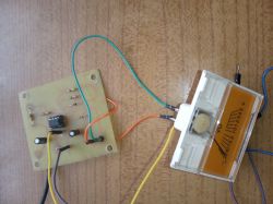
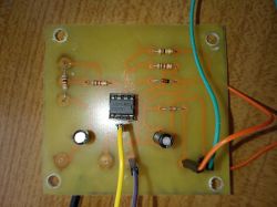
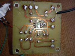
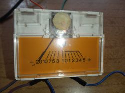
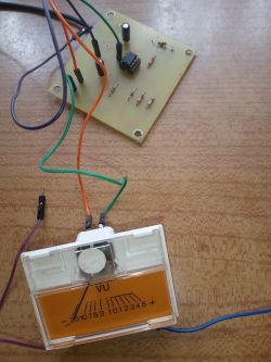
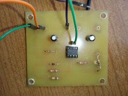
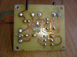
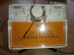
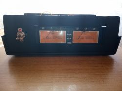
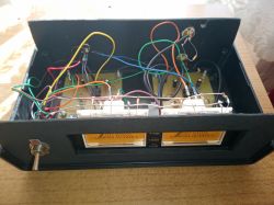
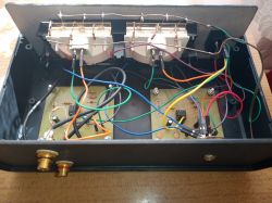
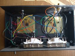
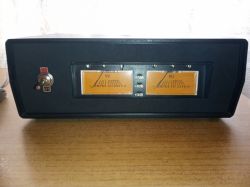
    Recently, I got my hands on two dial indicators. I used two such systems to drive these indicators Using LM358 IC for Dual VU-Dial Indicator System in Plastic Housing: Tips & Tricks based on the LM358 integrated circuit. I made the pcb project in TraxMaker. The whole thing is placed in a plastic housing.

    Using LM358 IC for Dual VU-Dial Indicator System in Plastic Housing: Tips & Tricks Using LM358 IC for Dual VU-Dial Indicator System in Plastic Housing: Tips & Tricks Using LM358 IC for Dual VU-Dial Indicator System in Plastic Housing: Tips & Tricks Using LM358 IC for Dual VU-Dial Indicator System in Plastic Housing: Tips & Tricks Using LM358 IC for Dual VU-Dial Indicator System in Plastic Housing: Tips & Tricks Using LM358 IC for Dual VU-Dial Indicator System in Plastic Housing: Tips & Tricks Using LM358 IC for Dual VU-Dial Indicator System in Plastic Housing: Tips & Tricks Using LM358 IC for Dual VU-Dial Indicator System in Plastic Housing: Tips & Tricks Using LM358 IC for Dual VU-Dial Indicator System in Plastic Housing: Tips & Tricks Using LM358 IC for Dual VU-Dial Indicator System in Plastic Housing: Tips & Tricks Using LM358 IC for Dual VU-Dial Indicator System in Plastic Housing: Tips & Tricks Using LM358 IC for Dual VU-Dial Indicator System in Plastic Housing: Tips & Tricks Using LM358 IC for Dual VU-Dial Indicator System in Plastic Housing: Tips & Tricks

    Film_presentation:


    Cool? Ranking DIY
    About Author
    elektronik.b
    Level 3  
    Offline 
    elektronik.b wrote 333 posts with rating 79. Live in city Lipce Reymontowskie. Been with us since 2014 year.
  • #2
    thereminator
    Conditionally unlocked
    Housing not too nice - good for some workshop power supply, not for an audio set element; the wires inside are routed sloppy, but the biggest error is the visible diodes illuminating the scales of the indicators. They should be covered at the front.
  • #3
    Anonymous
    Level 1  
  • #4
    conisl
    Level 11  
    Hello,

    Interesting project, today the displacement indicators are a rarity. The fact that you could use a better casing and a little more order inside, but you have to start somewhere. The next version will definitely be much better.

    greetings
  • #5
    CodeBoy
    Level 31  
    Overall a plus for wanting to :)
    As for the performance, there are a few mistakes, first, as already written, the LEDs are terribly tiring at the front, they should be covered from the front. If you have access to a thin aluminum plate, you can make grilles for the front of it and you will bake 2 birds with 1 fire (it will cover the LEDs) and it will be more compatible with the rest of the audio equipment.

    I don't like something about the scaling of the excursions, they work too much on the positive half of the scale, they should start more around -20 and move around 0dB. But for the image value, it is too often at the max :)

    as for the wiring inside, it is worth pinning them up with something to keep some order :)

    But overall a nice idea :)
  • #6
    zgierzman
    Level 31  
    CodeBoy wrote:
    I don't like something about the scaling of the excursions, they work too much on the positive half of the scale, they should start more around -20 and move around 0dB


    Because that's where the logarithmic amplifier should work ...

    Using LM358 IC for Dual VU-Dial Indicator System in Plastic Housing: Tips & Tricks
    Using LM358 IC for Dual VU-Dial Indicator System in Plastic Housing: Tips & Tricks
  • #7
    Anonymous
    Level 1  
  • #8
    398216 Usunięty
    Level 43  
    thereminator wrote:
    the error is the visible diodes illuminating the scales of the indicators. They should be covered at the front.
    CodeBoy wrote:
    LEDs are very tiring at the front, they should be covered from the front.
    They should not be on the front of the indicator at all. The indicator housing is specially adapted to be illuminated from the back - in the original, it is an all-glass bulb without a socket. This is also why there is a scale on a transparent film and behind it a matte diffusing pane. Surely, it would not be possible to replace the light bulbs without modifications to LEDs (due to a different distribution - the light through the LED is more focused - even in the case of matte housings), but ultimately the LEDs that the Author used also had to be (?) Somehow attached.
    I understand that this is the first construction from the board design to the finished device, so I will only say that the tiles with such a layout could be 1/4 of the size of the ones you made. For the future, try to miniaturize your designs.
    CodeBoy wrote:
    I don't like something about the scaling of the excursions, they work too much on the positive half of the scale, they should start more around -20 and move around 0dB
    In general, the time from the occurrence of a signal of a given level to its indication, as well as the time in which the indication falls after the signal ceases, is quite strictly defined for this type of indicators. Here it is just something that fans the clues to the beat of the music. There is no practical benefit from this.
    acctr wrote:
    There are numbers on the scale of the indicators, what do they mean?
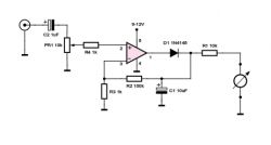
    A piece of a plastic grille "borrowed" from 9000 series and similar cassette recorders. In the original, there were lights for the MOMENTAL signal levels described on the grille. In the case of tilt indicators (having considerable inertia) and in application to a tape recorder in particular, it is important that the maximum value is not exceeded, because the tape distortion is not advisable and involves a loss of both quality and dynamics. For different types of tapes, the maximum instantaneous signal could reach different values - these lamps simply made it easier to set the appropriate level of the recorded signal.
    All in all, it is a pity that the author did not go a step further and copied this layout. Overall - the device works. Not how it could work to have some useful function (currently, it could only do effectively for a bedside lamp), not very neatly made (LED and no descriptions on the sockets on the back), no logarithm circuit, a switch and a mess that does not match the function and the whole device inside; but it works. Nothing else.
    I think that if the author uses all these words of criticism in practice - subsequent projects will be much better.
  • #9
    Gizmoń
    Level 28  
    You had to make full use of one LM358 chip instead of two, only half of each. How can amplifiers be wasted like this? :D Everything would then fit nicely on one PCB. If any amps are already left unused, it is good practice to pin their inputs to their states instead of leaving them "hanging".
    I used to have identical indicators, they probably come from some Polish tape recorder? As far as I remember, they can be highlighted from behind the scale. At the factory, there was a press-fit socket with a light bulb, which illuminated the entire scale very nicely. This could be used instead of making headlights which, as already noted, are a bit offensive. And the hands break terribly at the end of the scale, it would be appropriate to reduce the gain a bit.
  • #10
    398216 Usunięty
    Level 43  
    Gizmoń wrote:
    they probably come from some Polish tape recorder?
    I wrote above.
    Gizmoń wrote:
    As far as I remember, they can be highlighted from behind the scale.
    About that as well.
    Gizmoń wrote:
    At the factory, there was an interference fit with a bulb,
    And this too ...
  • #11
    Gizmoń
    Level 28  
    @ 398216 Deleted There is a quarter of an hour difference in time between our posts. It already happens that two users will write something similar at the same time, and it will only come out after sending. You do not have to list what who wrote, use ellipses, everyone can see it. The more so because only "1/3" of the post coincided.
  • #12
    398216 Usunięty
    Level 43  
    19 minutes is quite a lot. Even I - having some writing difficulties - don't post that much.
    As for 1/3 ... the fact that only 1/3 coincides is a relative value. If you actually read my post beforehand, the whole thing would be different - you would not repeat anything ... In any case, do not repeat my posts, because in fact you did not bring anything new - I admit you are right about one thing - use in the middle of the US and hanging in the air of walking out is a bad habit.
  • #13
    rosomak19
    Level 22  
    From prefabs, you can buy a nice module to control the indicators, and if you want to, you can find its diagram on the internet. Personally, I use it in my power amplifier to indicate the output power to which it has been calibrated with the gauges used, but there is no problem for it to work as an indicator of the input signal level. Because waving your clues just for waving them is a bit of a nonsense.
  • #14
    Stanley_P
    Level 27  
    398216 Usunięty wrote:
    19 minutes is quite a lot. Even I - having some writing difficulties - don't post that much.
    If you had actually read my post beforehand, the whole thing would have been different - you wouldn't be repeating anything ...

    Speaking of OT: on several forums, I saw a warning when posting a message if someone added a post to a thread in the meantime.
    And whether 19 minutes to write is a little or a lot - a relative thing. More than once I have created relatively short scribbles for quite a long time ;-) , sometimes a man leaves the computer in some matter, etc. In any case, I think that such a warning mechanism would be useful on the Electrode.
  • #15
    Tomek515
    Level 23  
    Such an indicator does nothing. It works 0-1. Let this maximum scale be practically unattainable. If you heal it a little, it will be cool.
  • #16
    klamocik
    Level 33  
    I had such a problem with the LED backlight for the bulb, I used a piece of silver; a half cylinder placed on the diode and a flat piece at an angle of 45 degrees from the face where the most light.
  • #17
    elektronik.b
    Level 3  
    Welcome back.
    Thanks for such comprehensive answers.

    1. As for the leds illuminating the scale (why didn't I hide them?), I just wanted to use them as a bedside lamp, because I often listen to music from the tower after 8:00 p.m. when it is already dark and it fits very well with the rest of the tower, so to speak I have full lighting of the desktop, besides, unfortunately I could not hide them in this transparent plastic above the scale and the bulbs were unfortunately too weak.

    2. It's a fact that there's a mess inside, but the next time I'll pin them down and put them in order with small clamps as for the case, unfortunately I didn't have a better one at hand and the front panel is made of 2mm cardboard, I had to do it because in a plastic one it was difficult for me to cut such a rectangle on these indicators.

    3.As for the indications of the indicators themselves, they are not connected to the amplifier, but to the normal, non-amplified audio signal, and between the control board and the Rca socket I connected a 390kom resistor because when I connected without a resistor, the tips were almost all the time at maximum with the music on and off the different music has different volume levels, e.g. when I hear from the radio tuner the directions stop at 0db maybe a bit higher and in the video I played the signal from the cd player and e.g. from the tape recorder they indicate +2, 3db.
  • #21
    bratHanki
    Level 35  
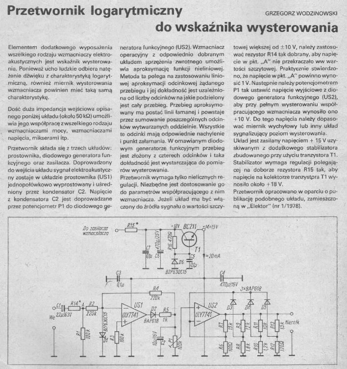
    Did you look at the link I provided at all?
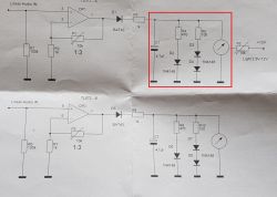
    Using LM358 IC for Dual VU-Dial Indicator System in Plastic Housing: Tips & Tricks
    Probably some correction of some elements in the amplifier will be needed, but I hope you understood what it was about.
  • #22
    elektronik.b
    Level 3  
    OKAY. I already understand where to add this PCB with diodes, but I don't know yet which elements need to be changed in the amplifier.
  • #23
    kiss39
    Level 38  
    @ elektronik.b I support and support. A nice design is worth modifying a bit and as colleagues write above about e.g. LED lighting, this type of equipment with "VU-Meter indicators", the lighting is warm, dimmed, the panel will give a brushed aluminum panel, which will be similar in size to the other DIORY segments of the SSL 0422 series. Large displacement indicators are a rarity, because equipment with such indicators is very expensive and visually desirable.

    Two popular scales are shown and discussed here: professional and consumer scales. Construction and performance of VU-Mater with a professional and consumer scale
    Audio drive indicator +4 dBu, -10 dBV - VU meter- https://www.youtube.com/watch?v=rnwqdbLC4jg
  • #24
    elektronik.b
    Level 3  
    Hello, after a long break.
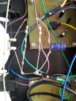
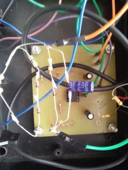
    I made this layout with diodes and these two resistors and a capacitor from post # 21 and I think that the indicators are working much better now, I also attach a new video after using this system is in post # 1.

    Using LM358 IC for Dual VU-Dial Indicator System in Plastic Housing: Tips & Tricks Using LM358 IC for Dual VU-Dial Indicator System in Plastic Housing: Tips & Tricks
  • #25
    398216 Usunięty
    Level 43  
    elektronik.b wrote:
    I made this circuit with diodes and these two resistors and a conductor
    And the level of "hacking" the interior has increased significantly ... You must always take into account that your index will not stay in the same place for ages. Every movement or even movement while rubbing the dust is a vibration. The more of them and the stronger they are, the greater the probability that something will eventually break or shorten ... So if you are already doing "spider's" then try to make the "spider" occupy as little space as possible and its connection with the rest ( stiffer, attached to the casing) was as short as possible and so thought-out as to prevent any possible migration of the spider inside the casing.
    If an element has legs a few centimeters long, it does not mean that they have to stay that way. Long leads in the case of THT elements (for through-hole assembly) are only to facilitate assembly. Nothing more*.

    * Only some THT elements in some applications are mounted on terminals longer than the necessary minimum. In your case, nothing like that happens, so the legs should be shortened to stiffen the whole.
  • #26
    rosomak19
    Level 22  
    How to refine a little and calibrate above all, so that it shows at 0 dB what the git is supposed to show. Well, unless it's just such an addition that something throws clues, no matter what they show.
  • #27
    elektronik.b
    Level 3  
    Well, it is soldered to the spider but everything is holding very tight, I even shook the casing a little and checked if there was any short circuit, but nothing like that.
    But as I wrote earlier, it depends on what signal source you play the music from and it also depends on what it sometimes shows 0db and sometimes a little higher, for example, on the video I played from a cd and from the tuner it shows a little lower from the tape recorder also differently, so I think it is good with these indicators.
  • #28
    398216 Usunięty
    Level 43  
    elektronik.b wrote:
    I shook the case a little and checked if there was any short circuit, but nothing like that.
    One of Murphy's laws is that anything that can go wrong will definitely break when you least expect it.
    elektronik.b wrote:
    I think it's okay with these indicators.
    As much as the clues are wagging.
    Such an indicator, in order to fulfill a role other than the visualization of the music level, would have to show SOMETHING SPECIFIC - the power, value of the signal, and in order to be able to do that, it would have to have a scale compatible with what it shows. In other words, it shows something there, but apart from saying that the signal from the CD is a LITTLE (because you don't know exactly how much) stronger than the signal from the radio.
    So fairy tales.
  • #29
    rosomak19
    Level 22  
    It would be best to plug it permanently into the preamp to have a constant load and then tune 0dB 0.775V on the oscilloscope, then at least for something other than wagging it would serve.
  • #30
    Tomek515
    Level 23  
    You keep jerking off these tips chaotically, but it's better. I have a comparison because I have factory equipment. I don't know, maybe it's just hard to calibrate but in this form it's like a colorophone - a visual effect. Nevertheless, I approve because there is something cool about these tips :)