Elektroda.com
Elektroda.com
X
This content has been translated flag-pl » flag-en View the original version here.
  • Audio spectrum display (ESP32, WS2812B)

    Hello everyone :)

    In particular, lovers of lights, illuminophonics, etc.
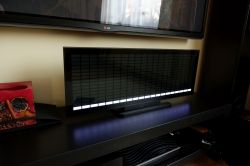
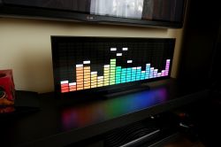
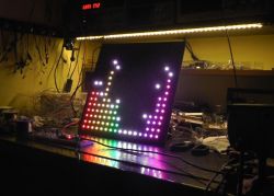
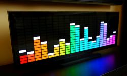
    The presented device displays the acoustic spectrum in the form of 20 bars, 16 points each. It's hard to call them a spectrum analyzer. I associate the analyzer more with a measuring device, although the frequency display is quite accurate here, which cannot be said about the level scaling, which changes anyway. But more on that below.

    Similar structures can be found on the Internet. However, most of them are unfinished in my opinion. Flashing LED strips glued to "something". And so the idea was born to build a nicer display referring in style to classic factory constructions, but in enlarged dimensions.

    The matrix is made of a 640 LED WS2812B strip. Due to the size of a single "pixel" 30 x 11mm, it is backlit with two diodes, which gives 320 light points.

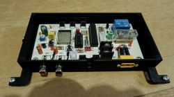
    The heart of the control system is the ESP32. This is actually my first project on this MCU and I'm just getting to know it. As for the program code, there are a lot of ready-made sources for building similar devices. I decided that there is no point in breaking open the door and I chose a ready-made one. https://github.com/s-marley/ESP32_FFT_VU
    Unfortunately, the code only works with version 1.0.4 of the ESP32 Arduino board. With higher versions there are problems with ADC sampling above 20 kHz.

    However, I made some modifications and fixes:
    - Changed ADC sampling from blocking loop to timer interrupt, which significantly accelerated program execution.
    As of today, I got about 20 FPS refreshing the matrix with the size of 16x40 LED and 29 FPS with the 8x8 matrix, and probably not more
    you have to, because the pillars will become "nervous".
    - Automatic audio level setting, but on the side of the FFT band values. Something like "ARW". The sound level differences between different music albums are significant and the sound input level had to be adjusted. The aforementioned "ARW" handles it quite well.
    The device is operated with an IR remote control. The learning IR receiver is based on Atmega8 or Atmega88. It is able to handle the most popular formats of remote control commands (Nec, Nec16, Nec42, Samsung32, sony(SIRCS) Denon, Sharp).

    There are 6 commands to use.
    1 - Switching on and off
    2 - Panel brightness +
    3 - Panel Brightness -
    4 - effects switching +
    5 - effects switching -
    6 - enabling or disabling "peaks"

    Only the IR receiver module is active during standby. After receiving the command to turn on the device from the remote control, the ATmega unlocks the ESP32 and turns on the power to the LED strip.

    Construction :
    Almost the entire structure is printed on a budget home printer from PLA, with a filling of 20%, in places densified to 90% for screws. The exception is the rear wall (HDF 3mm) and base (MDF 10mm).

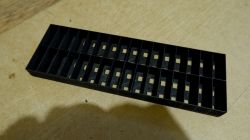
    LED compartments.
    Audio spectrum display (ESP32, WS2812B)

    They need to be painted white on the inside to diffuse the light better.
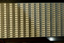
    Audio spectrum display (ESP32, WS2812B)

    Trial assembly of partitions and masking
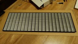
    Audio spectrum display (ESP32, WS2812B)

    Due to the limited size of the print, the casing frame is printed in pieces and then glued together.
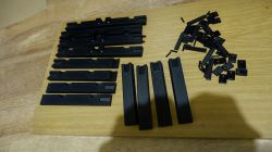
    Audio spectrum display (ESP32, WS2812B)

    Installation:

    Housing frame glued to tinted glass.
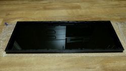
    Audio spectrum display (ESP32, WS2812B)

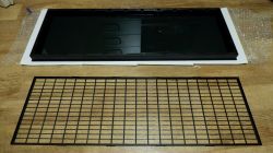
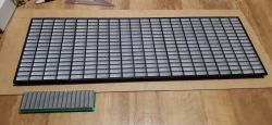
    Now the grille
    Audio spectrum display (ESP32, WS2812B)

    Audio spectrum display (ESP32, WS2812B)

    On the grille there are screens made of white PVC 160um. Obtained from the covers of office folders. So in pieces...
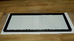
    Audio spectrum display (ESP32, WS2812B)

    It's time for partitions with glued and soldered LED strips. The partitions are not glued together to better adhere to the grille and the glass.
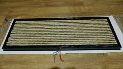
    Audio spectrum display (ESP32, WS2812B)

    Installation of elements pressing the partitions to the glass with the mask. These elements also center the partitions vertically.
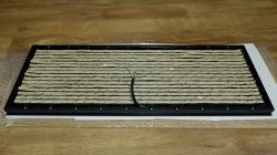
    Audio spectrum display (ESP32, WS2812B)

    Audio spectrum display (ESP32, WS2812B)

    The whole is closed with an HDF board with screws.
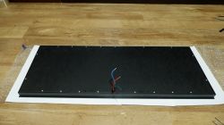
    Audio spectrum display (ESP32, WS2812B)

    Installation of vertical supports with base and electronics housing
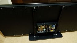
    Audio spectrum display (ESP32, WS2812B)

    Destination
    Audio spectrum display (ESP32, WS2812B)

    Audio spectrum display (ESP32, WS2812B)

    Audio spectrum display (ESP32, WS2812B)

    Another electronic board
    Audio spectrum display (ESP32, WS2812B)

    The whole is powered by a 5V 22A power supply.
    Panel dimensions 710 x 256 x 28 mm.
    Dimensions with base 710 x 280 mm.
    Source codes - Arduino IDE.

    Diagram. I hope there are no errors on it..
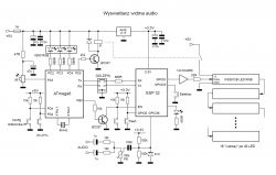
    Audio spectrum display (ESP32, WS2812B)

    A short action video. It still doesn't show the live effect.
    https://youtu.be/aGNrLPwe1e0

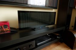
    Sorry for the quality of the photos. These blacks are hard to photograph...
    I am attaching the ESP32 source codes. Prototype code. it will probably be modified. And the source of the IR receiver
    And that's all in a nutshell... :)

    Cool? Ranking DIY
    Do you have a problem with Arduino? Ask question. Visit our forum Arduino.
    About Author
    efi222
    Level 13  
    Offline 
    efi222 wrote 166 posts with rating 550. Live in city Toruń. Been with us since 2019 year.
  • #2
    KJ
    Level 31  
    The workmanship is very nice, but in my opinion it lacks fluidity - maybe it's worth dividing the 640 LED chain into smaller sections and connecting it to several ESP lines, which should ensure faster refreshing.
  • #3
    tmf
    Moderator of Microcontroller designs
    KJ wrote:
    The workmanship is very nice, but in my opinion it lacks fluidity - maybe it's worth dividing the 640 LED chain into smaller sections and connecting it to several ESP lines, which should ensure faster refreshment.

    For 600 LEDs you can theoretically achieve 55 FPS in a chain, so there should be no problems.
    Very aesthetically made design. The end result is really nice.
  • #4
    KJ
    Level 31  
    tmf wrote:
    With 600 LEDs you can theoretically achieve 55 FPS
    Theoretically... practically the CPU has other things to do in the meantime. Also "theoretically" ESP32 has 2 cores, so you can delegate one to send data to the LEDs, the other to the rest. It should be noted, however, that my colleague probably does not fully understand advanced programming because this mega 8 is theoretically completely redundant here, but well - arduino is exactly what its long-term side effects are :D
  • #5
    efi222
    Level 13  
    Advanced programming is out of the question, because I am an amateur not professionally connected with electronics, and even more so with programming, which I have been learning for probably 5 years. I build my devices and I'm glad that they work more or less as I would like. And they are at the level of my current knowledge :)
    And the Arduino IDE allows people like me to create something quite quickly to the joy of creating and its effects :)
  • #6
    KJ
    Level 31  
    5 years is quite a lot ;) Maybe it's a good time to take care of a more developmental environment than arduino ide and assembling everything from ready-made blocks?
  • #7
    efi222
    Level 13  
    There used to be a campaign against Bascom... Now Arduino is falling out of favor..
    Besides, my friend at my age, I'm not likely to look for a more developmental environment. I don't think I even need it.
    Where do you see Arduino blocks? A plate made especially for this project. :)
  • #8
    KJ
    Level 31  
    efi222 wrote:
    There used to be a campaign against Bascom...
    And she was very right - I wasted 20 years of my life on this damn thing.
    efi222 wrote:
    Now Arduino is falling out of favor..
    For the same reason as bascom, it is justified.
    efi222 wrote:
    Where do you see Arduino blocks? A plate made especially for this project.
    And that's praiseworthy :) I was referring more to software "blocks". ;)
  • #9
    maviozo
    Level 10  
    It looks great. I like it in almost every way. He can possibly try to use these colors more creatively, we have such a wide range and basically it's just either falling white blocks or the color of the "sound level" set for the bar. Maybe add some encoder and make tetris on it? Or snejka? :D
  • #10
    efi222
    Level 13  
    I also started with Bascom... And now?
    Well... Half the world of amateur builders writes in the Arduino IDE. They share their scribbles with the rest of the world.
    I think that's good. It encourages beginners to create. Even if it's copy/paste at the beginning.
    You have to start somewhere. Competitive environments, in my humble opinion, are for professionals.
    In a moment, an assembler guy can come in here and say that C is sub-optimal, etc... And so on and on :D
    And the blocks? The blocks are everywhere. Aren't libraries such building blocks?

    Added after 13 [minutes]:

    maviozo wrote:
    ... Maybe add some encoder and make tetris on it? Or snejka? :D

    Well, if someone likes it, they can add Tetris to the code :D
    There is a YouTube muse on YouTube. So-so, weak to demonstrate..
    But if I include, for example, Andreas Vollenweider, the album Behind the Gardens Behind the Wall Under the Tree, then with the size of this spectrum it is a mini spectacle :)
  • #11
    KJ
    Level 31  
    efi222 wrote:
    Competitive environments, in my humble opinion, are for professionals.
    Virtually every manufacturer of microcontrollers offers a free environment for them. Is the arduino good - for starters, the problem is that people get stuck in this invention for many years because they say that other environments are "competitive" nothing more wrong but the arduino is constructed in such a way that people are reluctant to leave the comfort zone they created in it and that is 100% wrong ;)
  • #12
    ArturAVS
    Moderator HP/Truck/Electric
    Very nice workmanship, show the 20Hz-20kHz sweep, it will be possible to assess the real usefulness.
  • #13
    Gienek
    Level 37  
    Very nice workmanship, all materials available and the display can be repeated by an intermediate hobbyist. And this is the purpose and principle of publication in the DIY section. However, the discussion "about the superiority of Easter over Christmas" should not take place in this section. Or maybe the gentlemen who criticize the use of Bascom or Arduino will show their developments? We will see and evaluate then whether it is really worth moving to a higher programming environment to quickly make a device that brings so much satisfaction.
  • #14
    Janusz_kk
    Level 36  
    Gienek wrote:
    However, the discussion "about the superiority of Easter over Christmas" should not take place in this section.

    Exactly, pointless discussion here, maybe a moderator will cut it to a new thread?
    And for the display praise and plus, nice workmanship and some electronics also had to be handled.
  • #15
    damian1115
    Level 35  
    efi222 wrote:
    I am an amateur not professionally related to electronics, and even more so to programming, which I have been learning for probably 5 years. I build my devices and I'm glad that they work more or less as I would like. And they are at the level of my current knowledge

    And that's how it should be, the most important thing is satisfaction with what you've done, and what's more, you did it yourself, being an amateur.
    There are a lot of people on the forum professionally related to electronics and programming, and it's easy for them to say, and criticize us amateurs for things that do not come easily to us.
    To quote a colleague:
    Gienek wrote:
    Very nice workmanship, all materials available and the display can be repeated by an intermediate hobbyist. And this is the purpose and principle of publication in the DIY section. However, the discussion "about the superiority of Easter over Christmas" should not take place in this section. Or maybe the gentlemen who criticize the use of Bascom or Arduino will show their developments? We will see and evaluate then whether it is really worth moving to a higher programming environment to quickly make a device that brings so much satisfaction.

    I completely agree with his opinion, and I agree with his statement.
    The design is done nicely, aesthetically, and I like it very much. You put a lot of work into it and it deserves praise.+++
  • #16
    efi222
    Level 13  
    Thank you friends for the kind words :)
    I've been building it since last fall. Lots of different problems and tests. Test prints, screen selection, distance from the screen and more...

    ArturAVS wrote:
    Very nice workmanship, show the 20Hz-20kHz sweep, it will be possible to assess the real usefulness.


    At the request of a friend, videos with the generator. I don't have a hardware generator, so I used a PC program. I shot handheld so it shakes a bit :D

    the beginning of the 20Hz spectrum with a significant drop. At 40 Hz, it's still pretty good.


    the entire first bar 46Hz


    1kHz. Watch your ears... :)


    18kHz. Usable maximum.


    20kHz. Sampling limit (40kHz). Practically, such sounds probably do not exist in music anymore,,,


    Sweep. Pay attention to the ears...


  • #17
    ArturAVS
    Moderator HP/Truck/Electric
    You see! And I like it, it is not only a trinket but also a useful device.
  • #18
    efi222
    Level 13  
    I've done this kind of research before. That's why in the description it says that the frequencies are ok. It's just difficult to determine the sound level that "ARW" changes, making sure that the top bar fits the entire height of the display. Of course, within reasonable limits :)
  • #19
    Janusz_kk
    Level 36  
    efi222 wrote:
    It is only difficult to determine the sound level that changes "ARW"

    What is your scaling of the bar relative to the signal? looks linear and should be logarithmic, then ARW would be unnecessary.
  • #20
    efi222
    Level 13  
    The scaling of the bars is linear. I was supposed to get around to it sometime and see it with a logarithmic scale. The code still needs polishing.
  • #21
    BVBek
    Level 12  
    And I will ask for a more detailed explanation of the very aspect of optics.
    Have you used any diffusion foils?
    This tinted pvc / hips / pet is immediately black or was there some foil glued on, and if so, how much % of permeability did you use?
    Is the brightness of these double LEDs during the day on a sunny day satisfactory?
    BTW. Great project.
  • #22
    efi222
    Level 13  
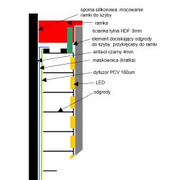
    So I felt that these black photos would not be very legible. The windshield is tinted glass. Antisol black 4mm. Looking from the front, there is a glass, a grille (pixel contour grille), a diffuser made of white PVC, 160um thick, and a chamber with LED. When I get home I will send additional materials and explanations. ;)

    Added after 5 [hours] 48 [minutes]:

    Continuing..
    As for the brightness of the panel, it seems to be sufficient with a large margin. I had some concerns and prudently put antisol black 4mm on the headlamp. It's hard for me to assess how much % it dims, but maybe about 30. I have a room with a north window. During the day, a PWM value of 30 (8 bits) is sufficient. In the video with the generator there is just such a brightness.
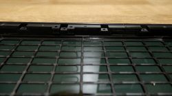
    The diffuser should be as thin as possible, because there is a small distance between the chambers. Through the one I used up close, you can see "barely" the red points of the red LEDs. With a thicker one, light can penetrate into adjacent pixels. Three layers of tracing paper had a similar effect, but it was a bit too thick. Even pressing hard didn't help. There are two walls between the pillars. This is due to the construction and it is about 1.5mm. Between pixels horizontally about 0.8mm. The grille has a reserve of covering these walls. horizontal masking 2mm, vertical 3.
    I'm not very good at drawing on a computer :) but I scribbled a section of the side wall. Maybe that will be helpful.
    I do not use plastics in my constructions. However, the glass is more resistant to scratches. You can look at the NTP watch design for comparison. There is a black 6mm antisol on the front. And you can't see the inside at all. Grille grilles shine through in the spectrum. But this is where it has its charm :)

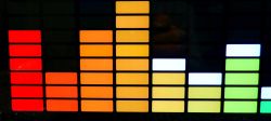
    Pixels close up
    Audio spectrum display (ESP32, WS2812B)

    Overview sketch. Sidewall
    Audio spectrum display (ESP32, WS2812B)
  • #23
    398216 Usunięty
    Level 43  
    A lot of work but the execution and the end result are sensational. You get 1000 points from me for a job well done.
    And finally, a little request; Do me a favor and paste the function in the program when the bars are green up to 3/4 of the height and then three yellow and red at the end. Then it will be a "real" level meter... ;)

    ("true" due to ARW and linear scale of course)

    Regards.
  • #24
    ArturAVS
    Moderator HP/Truck/Electric
    In fact, I'd take ARW off and scale to dB. I will give you 1000 points due to the amount of work you put in and the end result.
  • #25
    efi222
    Level 13  
    Gentlemen 398216 Deleted and ArturAVS thanks for the points :)
    The soft is in beta 1.0 and I will definitely tinker with it, although the effect you can see is very satisfying to me. Once I finished this construction, I put it in its final place, sat comfortably and fired up this contraption. I was supposed to go smoke earlier but unfortunately an hour passed before I got up :D
    And it's not that I'm praising what I've done. Even my wife, who usually acknowledges my inventions in the style: "and more lights" was interested in what this device is for and what it displays ... not to mention my grandchildren..
    And when it comes to displaying the colors of the bars, there are virtually no limits. These are the technologies we have now and what was unattainable 30 years ago can now be realized in the privacy of your home ... And I am glad that I lived to see such times :)

    If any maniac of light lines wants to repeat this project, I will help if possible.
    I have some higher resolution pictures as well.
  • #26
    CMS
    Administrator of HydePark
    Something beautiful. I want two of these for Christmas :) (one per channel), but even though I have the skills to copy this miracle, the time is completely lacking. I'm guessing you won't be building any more :) .
    Would you be able to estimate construction costs from scratch, along with approximate time?
  • #27
    398216 Usunięty
    Level 43  
    I'm guessing the construction cost was not taken into account. As in any DIY construction that you do for your own satisfaction (
    efi222 wrote:
    I was supposed to go smoke earlier but unfortunately an hour passed before I got up
    ) and have fun with the target effect. I know for myself - if I had to sit down before or even during the construction work and calculate even approximately "how much it will cost", I probably wouldn't do anything.
  • #28
    CMS
    Administrator of HydePark
    I want to know what the approximate budget is. It doesn't matter if it's 300PLN or 2000PLN, but I want to know :) .
  • #29
    efi222
    Level 13  
    Surprisingly, the project was created completely by accident.. :)
    Now it will be something like "I was captivated by your story" :D
    In short: A friend asked me if I would make LED illumination. But not like many simple projects where the LEDs flash zero-one, only with the simulation of the inertia of the bulbs.
    And so it began. At the beginning I used analog filters with the use of ATmega as a simulator of these bulbs. It worked like that. Mostly poor filter separation. So I read about FFT. Unfortunately, Atmega couldn't handle it too much, so we had to reach for a stronger processor - ESP32. The illumination worked like a dream. Everything digital. Up and down inertia adjustment. Selection of bands for each channel. Configure everything properly.
    I had a few meters of WS2812b strip. If I already have a working FFT, why not try hooking it up? I glued it on a piece of HDF in the form of 16 x 16 LEDs. I fired it up and wow effect.
    Audio spectrum display (ESP32, WS2812B)
    And so it began. First, experiments with focusing screens and the LED distance from them. This is where I stayed the longest. Tracing paper gave good results, but only three layers gave good dispersion. Distance from LED 17 - 18 mm. but the tracing paper was a bit too thick and the light escaped slightly to the neighboring fields. I had a fragment of a yellow cover from an office folder in my scraps. I put it on and that was it. The minimum clearance is but negligible. With good adhesion of the LED partition, it is imperceptible.
    The prints went faster. Home printers print as they print. The most difficult were the partitions. Printed in two bars after assembling 10 such pieces, the LEDs had to fit into the holes on the bottom. And since the LED spacing on the strip is 1.666 .. no grinding was necessary. It is better to make this dimension a little smaller. The belt is easier to slightly "wave" than to stretch (stretching is practically impossible). But also without exaggeration.
    Now costs:
    I ordered two rolls of WS2812B from the Chinese, because I had some sections.
    And here was another mistake.
    LED strips should be from the same batch, or at least the same manufacturer. They shine differently from different manufacturers. This is especially noticeable on white. (This also translates to colors, although not as much). These are not big differences and you can't see it on the unrolled tape, but on such a matrix it is visible.
    Sum sumarum I ordered three extra rolls from another seller and it was ok :)
    I'm going to decorate the Christmas tree this year with what's left :D

    estimate:
    LED strip 3 rolls approx. PLN 180 from China
    Glass Antisol black 4mm PLN 100 with shipment from Gdańsk from a glazier
    Filament about 1kG PLN 50
    5V 22A power adapter PLN 85
    total 415
    the rest is electronics, paint to paint the partitions inside, glues, HDF for the back wall, MDF for the base, screws, black silicone and other gadgets.

    I think that about 500 - 550 PLN should be enough for everything.
    I don't think I missed anything.

    @CMS I don't know if you read the dimensions of this contraption, but the stereo version, i.e. two such panels next to each other, will occupy almost 1.5 m in horizontal space :) And it's hard for me to pinpoint the timing. There was too much experimentation with the prototype. It takes a lot of time to print. I printed with a 0.4 nozzle with a layer of 0.28. The double baffle (two bars) took about 4 hours to print.

    Added after 1 [hours] 10 [minutes]:

    I also found a comparative photo of the Chinese spectrum on green LEDs for PLN 150 with what I managed to produce.

    Added after 1 [minutes]:

    Audio spectrum display (ESP32, WS2812B)
  • #30
    398216 Usunięty
    Level 43  
    efi222 wrote:
    I don't think I missed anything.
    Exactly - every DIYer skips the most important part of the cost of the device made - elements used during tests, time for designing fixes and prototypes. Then he throws himself casually - "You know, it was a bit of work, but I fit in a hundred". And how about all the failed prototypes, mistakes that required repeating everything from the beginning and hundreds (!) hours of conceptual work? How much will it cost? I do not want to negate the author's calculations here, nor do I want to discourage imitation - I just would like to make those "outside the industry" aware that no one will appreciate electronics who has not tried it. As I wrote earlier - the costs do not count, the important fun is that it worked.