


Of course, similar posts can also be obtained in single or dual colour and in any of the available LED light colours.
It took a bit of "scouring" of AliExpress, because just such a set of colours (and in such quantities of each) - contrary to appearances - is not the most popular. If anything, it is more common to come across offers of similar BAR LED indicators, but instead of the first (lowest) green LED being inserted in (as if otherwise...
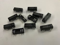
There are, of course, similar gauges on offer from Ali.... "by the metre". Hardly any that come in different colours - all of one shade, red, green, blue, etc., right down to the most varied colour sets or different numbers of LEDs. If someone is interested in the offer, but, for example, 10 LEDs is not enough - there are also posts half the size, also in one or two colours. And since (and I have included this in the topic) IT IS ALSO POSSIBLE TO CONNECT LM391* DRIVERS in series and obtain indicators with a greater number of LEDs (and, of course, a greater range of indicated sensitivity levels) - I believe that the field of possibilities is huge.
I based my design on a typical application for an IC specifically designed for such applications, the LM3915. The application note of the chip explains everything. In addition, it contains a rich description of all possible applications, which means that this chip (now only produced in China), even today - many years after its premiere on the market - can still be an interesting proposition. I chose one (tested by myself many times in several earlier devices, but still with single LEDs) found years ago in one of the first issues of "Electronics for All".

As I wrote - the schematic has been verified by me more than once in such a circuit and has worked great. So all that was left to do was to work out a proper drawing of the paths to it, add the LED posts and.... done.
Of course, there were a few minor mistakes. Unfortunately, the years have taken their toll, and the board with the LED bars had to be mounted in a rather unusual way.... Anyway, we managed to design the whole thing into a compact module of relatively small dimensions.


For those who may be interested - the drawings of the paths are suitable for the production by thermal transfer of the boards enabling the assembly of such a module as in the following pictures. Simply print them in their original size and transfer such a print to the laminate.
One could talk a lot, but since "one picture is worth more than a thousand words", I will present my work on making the prototype below in the form of a photo report.
Applying the laminate cut to size to the print (Kapton adhesive film):

After 'ironing' and removing the paper (I use pages from women's monthly magazines - already read, of course, and with my Wife's permission, made available to me for this purpose):

A thermal transfer made in this way is already suitable for etching (available etch at any electronics shop):


Once the superfluous copper has been completely removed, the toner needs to be washed off, in my case with f-brand "Dragon" all-purpose solvent. Unfortunately it has one disadvantage - each successive batch has a slightly different composition and sometimes it dissolves the toner completely and without any problem from the plate, and sometimes (different batch) it only "softens" it and it takes a little longer to remove it:


After removing the toner, it would be a good idea to coat the plates with a rosin solution in IPA. One, this will make it easier to solder the components later, and two, it will protect the tracks from oxidation.

The rosin coating needs to be COMPLETELY dried before the next step - in my case I put the tiles on a hot electric cooker (induction is not suitable) for about 45 seconds. As soon as you start to see a slight vapour rising from the tile - I turn off the power and leave it until the cooker cools down.
Thus protected it is ready for drilling and soldering - the rosin coating will effectively protect the copper for decades against airborne contaminants (sulphides, oxides, etc.).
For a high-speed drill with a precision drill chuck, insert a WIDIA drill bit (I usually use a 0.8mm diameter for most of the through-hole components).

And we drill. If we have the option, it is a good idea to set the speed to max. - A widia drill performs best at at least 10,000 rpm.

Holes drilled in this way retain their ideal shape and the pitchfork drills ensure that, thanks to the long life of the pitchfork, the copper around the hole, the 'pad', is not damaged, facilitating correct soldering of components.

We have the boards ready to assemble the components. However, before we switch on the soldering iron, it is a good idea to clip a few critical components and check the order in which they should be soldered. In this particular case, this caution applies especially to the board with the LED posts.
Soldering it with the LM3915 and LM741 (or a similar circuit with a single operational amplifier structure) should always be started by soldering the least stand-off components on the board.


It is a good idea to supply your soldering iron with a tip that is as precise as possible - with a sharp, thin tip.
After soldering the lowest components, it will be the turn of the higher and higher components - this will make the assembly and the soldering itself easier, especially if you do not use a solder holder for the board to be soldered.


It's time for some fitting. The LED display board attaches to the controls using angled goldpin strips. Depending on what is available (although the ones in the prototype are the easiest to find) you will sometimes need to shorten the pins going into the display board. The goldpins I've used allow the pins to be left without cutting their length - the protruding ends fit perfectly under the displays.


After soldering, the whole thing looks like the following:


You can think about mounting the module to the faceplate. My suggestion requires two M3 mounting studs in "girl and boy" design, i.e. with female threads and a threaded pin. For a perfect fit with the faceplate on the inside of the case, 8mm long dowels will fit.


The size of the stereo indicator module made in this way is, looking at the display panel - 38mm wide, 35mm high, and the depth (from the front of the indicator to the end of the control boards (not including the power and input signal connectors)) is about 55mm. Note!6cbb22087 Since the distance between the driver boards is small (approx.. 12mm), capacitors should be selected as "low" as possible so that there is no possibility of their housings short-circuiting with the pads of the adjacent board.
The module is powered from 12V (if different, changes must be made to the application components - see the LM3915 chip data sheet for more. For example here: http://www.datasheetcatalog.com/).
In my case, I chose the 3915 from the LM391* family, as this chip works best as an amplifier drive indicator. If someone wanted to use such an indicator, e.g. for a tape recorder, it would be appropriate to use the 3916, which has a "stretched" section of sensitivity around 0dB. This will allow a more precise setting of the recording sensitivity without the danger of overdriving the signal.
Now about the sensitivity adjustment of the indicators themselves. In a design like the one in the diagram, the signal sensitivity will be around 0dB (0.775V), and to some extent this value can be varied by selecting resistor R13 (according to the markings in the diagram). However, in a situation where we would like, for example, to connect this indicator to loudspeaker outputs, we cannot do without a voltage divider selected according to the maximum voltage at the amplifier output adjusted to +3dB. In such a case, the indications of the indicator (leaving R13 as in the diagram) will accurately show the amplifier's state of drive, taking into account momentary "peaks" for the loudest moments of the recording.
And how does it work in real life?
Well, more or less as follows.
The value of the input resistance is approximately equal to R13, so you can in many cases ignore the influence of such a large one when connecting the input.
As you can see below, full drive is possible 'from the finger':
The rise and fall times of the indications are adapted to the applicable standards. The bar reaches its maximum indication in about 1/10 of the time it takes for all LEDs to go out. This ensures that we do not "miss" momentary "pins" in the signal and, in turn, the slow descent enables a non-fatiguing observation of the indicator. If it reacted faster, instead of a fully-fledged indicator, we would rather have a flicker whose flashing for the observer did not change depending on the signal value enough to notice the difference, for example, between musical signals of -10 and 0dB. This is, unfortunately, a common mistake among the "Young Talented", for whom the flashing itself is the most fun, while it is difficult to call such an arrangement useful as an actual level indicator.
A few words about the LM741 application. This circuit acts here as a signal rectifier; it converts the variable music signal into real-time DC voltage fluctuations. In addition, the diode chip (1N4148 or any low-power silicon diode) provides a QUASI-IDEAL rectifier circuit. That is, it includes both halves of the signal - above and below zero - in the output voltage value.
Finally, the method of connecting the power supply.
In the prototype, I used two separate power and input signal sockets for each channel (of each board). Of course, the power supply can be shared between the two control boards, so there is nothing stopping you from connecting the respective solder fields to each other (ground and plus of the power supply) using silver wire. However, there are, after all, power amplifiers with a bridge output for which neither speaker output is connected to ground. In this case, the two boards must be electrically separated - if the ground or power supply were shared, this could lead to damage to the amplifiers connected to the indicator, or to the indicator boards themselves. Separate supply voltages are required for this type of power amplifier. In typical amplifiers with the loudspeaker output ground connected to the amplifier supply ground, the supply points of both indicator boards can be combined, as I described above.
To conclude the topic, I attach videos of the indicator connected to a tuned generator - the sensitivity drop for 1Hz is about -3dB, increasing as the frequency increases. Above 10Hz the sensitivity is already constant, up to about 60kHz:
As I've already written, the LM391* family of circuits includes three models - the 3915, with a change in active diode every 3 dB, the 3916, with a stretched indication area for 0 dB, and the 3914, whose diodes light up linearly as the input voltage increases. For each of these, the applications are different, allowing a suitable implementation to be selected according to need. The 3914, for example, can replace a voltage meter with a resolution of 1/10th (e.g. for 1V only the first diode is lit, for 4V four (or the fourth - it can be switched to light only the diode for the maximum currently measured voltage, or a series of diodes are lit from min to max of the specified voltage), and for 10V the last (or all). There are also many additional applications to be found in the DS of the circuit - e.g. allowing one to get an indicator from two LM3915s consisting of 20 LEDs with an increased dynamic range displayed. Or a circuit where exceeding a certain measured voltage value causes an alarm in the form of flashing of all LEDs. Thus - a simple circuit with enormous possibilities depending only on the imagination or requirements of the designer. I encourage you to familiarise yourself with these circuits and I hope that this topic will contribute to the interest in this family of LM.
Best regards.
Cool? Ranking DIY

