logo elektroda
logo elektroda
X
logo elektroda
ADVERTISEMENT
Treść została przetłumaczona polish » english Zobacz oryginalną wersję tematu
  • Hello colleagues.

    I haven't published anything for a long time. I spend more time on mechanics in the workshop. Milling machine, lathe.
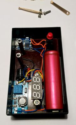
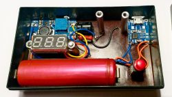
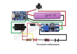
    Today, a simple meter, a Zener diode voltage measuring instrument. Diagram from the Russian-speaking forum. Both the simple diagram and the execution of the device. Three ready-made modules for a few zlotys and one resistor, capacitor and a few centimeters of cable. It has an external battery charging.
    It works immediately after assembly. Measures diodes up to 30V. One note when doing this
    check the correctness of + - and U wires on the display PCB. There are different colors and sequence of leads.
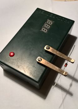
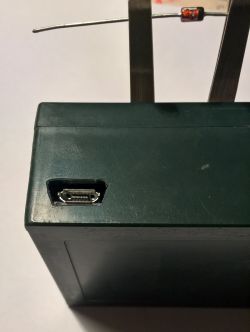
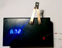
    Zener voltage measuring instrument. Zener voltage measuring instrument. Zener voltage measuring instrument. Zener voltage measuring instrument. Zener voltage measuring instrument. Zener voltage measuring instrument. Zener voltage measuring instrument.

    Cool? Ranking DIY
    About Author
    pustan
    Level 19  
    Offline 
    pustan wrote 629 posts with rating 1685, helped 17 times. Live in city Bielsko-Biała. Been with us since 2005 year.
  • ADVERTISEMENT
  • #2 18932274
    398216 Usunięty
    Level 43  
    This is called "Creative use of ready-made modules".
    Simple but effective and most importantly - cheap.
    Technical question:
    How often do you need to tighten loose screws of the contact contacts?
    And the second - more technical: What current do you measure the diodes with and is it matched to the diode power?
  • #3 18932515
    Justyniunia
    Level 36  
    Nice stuff. For a long time, I have intended to build something like this, because I have a whole drawer of unidentified zener diodes.

    These contacts are a good idea, but I propose a screw on the bottom, a nut on top, a contact, a spring and finally a self-locking nut.
  • #5 18932577
    M. S.
    Level 34  
    I suggest using a converter with current stabilization. Lead the current adjustment potentiometer outside the housing. Draw it a scale or turn on a milliammeter and you can even play characteristics. This could test other diodes, from simple rectifiers to LEDs.
  • #6 18932769
    Stanley_P
    Level 28  
    I have already spoken on a similar project before. I understand that self-making from various "scraps" lying in drawers - the joy of the hobby and "action" is priceless. However, I just wanted to note, because maybe not everyone knows (I didn't know until recently ...) that for only a dozen or so $ you can buy ready-made testers that can be used to measure not only Zener diodes, but also most of the discrete semiconductor and RLC elements. With accuracy, I consider it too sufficient in the workshop of an electronics hobbyist, or even in the RTV service (if there are still such ;-) )
    Even if the presented device could measure diodes with a voltage> 30V, e.g. up to 200V (the aforementioned Chinese testers also measure up to about 30V) and / or allow the mentioned taking of characteristics ... The only question is how many times do we need such measurements in practice ... and how often do we measure zener diodes - in the sense of measuring / checking the zener voltage ... IMO most often in service practice we simply check with a multimeter whether the diode has a short circuit and whether there is a voltage drop of about 0.6-0.7V in the conduction direction (the latter does not yet guarantee that the diode is in good working order, but usually yes).

    Justyniunia wrote:
    Nice stuff. For a long time, I have intended to build something like this, because I have a whole drawer of unidentified zener diodes.

    If most of the diodes are probably
  • #7 18933182
    pustan
    Level 19  
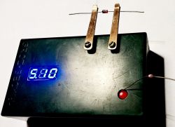
    I measured the diode measurement current, it is 10mA. If we mount the diode the other way around, it will measure us and display the voltage drop in forward direction. I do not tighten the screw. There is no such need because they do not loosen. While threading the posts for the contacts (phosphor bronze), I tapped M3 (2). The thread is tighter so the screw cannot be unscrewed. The contacts are in the so-called duckbill.
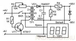
    But you can also put the diode on the contacts and the measurement is the same. Below is an attachment-photo for the tester up to ~ 100V

    Zener voltage measuring instrument.
  • ADVERTISEMENT
  • #8 18933221
    pikarel
    Level 38  
    The unquestionable advantage of this Zener diode tester over the "all-calling" tester is the measurement time;
    when measuring unidentified "shortcomings" - @Justyniunia wrote about it - waiting 5 seconds in TC-T4 is too long, with this instrument the measurement is immediate. I guess most electronics have something like that (I do) in their junk :)

    In the "all-teller" tester, a long measurement time is acceptable, but when measuring eg a transistor; this time is the total measurement time for many parameters, including electrode identification.
  • ADVERTISEMENT
  • #9 18933546
    Marian B
    Level 38  
    The device seems simple, because it performs only one task, but it will certainly be useful. Nice made.
    However, quite technically advanced components, an inverter, a voltmeter are used. Battery power in such a tester, in my opinion, not practical in a longer time of use.
    In addition, there is a housing, buttons, battery, connectors, screws, etc.
    All in all, quite a complicated device used for only one operation, measuring the Zener voltage in a fairly small range (up to 30V), it is even impossible to regulate the current.
    In my opinion, when doing "so much trouble" it is worth building a more universal device / tester, for example:

    https://www.elektroda.pl/rtvforum/topic3390653.html#16780245

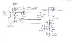
    It is an LED and Zener diode tester in one, a measurement range of 290V, and the ability to adjust the test current. If the system for detecting the connection direction of the tested LED and the protection against electric shock is omitted during construction, the scheme will be very simple, as shown in the figure below:
    Zener voltage measuring instrument.
  • #11 18933744
    Stanley_P
    Level 28  
    Marian B wrote:
    The device seems simple, because it performs only one task, but it will certainly be useful.

    Exactly, this is how I drip: useful how often? I repair some equipment, but so to speak: I had to measure the Zener voltage just recently, but probably for the first time in a good few years. In a switching power supply - I was not sure about the efficiency of the diode (you know what it is like with measurements in the system), so I desoldered it. The marking seemed to point to 55V, which is beyond the range of the Chinese "all-talking" tester. So I assembled a measuring system for a quick one, consisting of: a workshop power supply (up to 100V), a resistor of several dozen k? and a multimeter as a voltmeter. In total, it turned out that the diode is on 18V, which was confirmed by a closer analysis of the slightly blurred marking, and then also confirmed by the Chinese testers ;-)
    However, even if I needed to test a larger number of diodes once / sporadically, e.g. undefined ones lying in a drawer (this is about the measurement speed - in fact, I agree here), I would probably use just such a "measurement set" (possibly supplemented with a milliammeter), instead of losing time to build a "specialized" device that I will use every few years ;-) Unless I would run a Zener diode warehouse ;-) - then I would probably try to do something, but with more possibilities, e.g. as he presented @marian B .

    pikarel wrote:
    waiting 5 seconds in TC-T4 is too long, with this device the measurement is immediate. I guess most electronics have something like that (I do) in their junk

    Ie. do you have "all-knocking" testers, or specially made for zener diodes?

    EDIT. One more thing:
    pustan wrote:
    I measured the diode measurement current, it is 10mA.

    And it depends on the Zener voltage of a given diode ... Assuming that the DC / DC converter used has 40V at the output (well, it should be written ...), and if I can see it correctly in the assembly diagram in In the first post, the resistor connected in series with the measured diode is 2.2k? (three red stripes) - the maximum current in the system can reach about 18mA (short circuit). If the "zener" is 30V, the current will be about 4.5mA, which results from Ohm's law ...
    Quote:
    If we mount the diode the other way around, it will measure us and display the voltage drop in the forward direction.

    Normal, the same is measured by the Chinese "all-in-one" microprocessor tester.
  • #12 18934071
    pikarel
    Level 38  
    Stanley_P wrote:

    pikarel wrote:
    waiting 5 seconds in TC-T4 is too long, with this device the measurement is immediate. I guess most electronics have something like that (I do) in their junk

    Ie. you have "all-knitting" testers, or specially made for zener diodes.

    Both.
    Testerek "omkomiak" I have for points from the Electrode.
    "Made" (from 30 years ago) I have in a small box with a measurement current switch; I made it for the purpose of measuring Zener diodes above 20 V, often used in TV sets (canisters). It has a voltage converter inside on a small cup core, the output is about 100 V when powered by 12 V.
    I measure the voltage with any multimeter, this is not a NASA laboratory, but an efficiency tester (or operating voltage) of a factory-removed element from the device.
  • #13 18936149
    SylwekK
    Level 32  
    I do not deny the tester's performance, it is always a kind of satisfaction with the made tool. But is it worth it? As colleagues have mentioned, such a diode is not measured often enough, most often it is possible to segregate it. Perhaps the author often needs to measure, it's ok, although he probably already has a device ready to test even a kilogram of LEDs in a few minutes, like most electronics ;-)
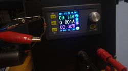
    After all, an ordinary power supply with adjustable voltage and current does the trick :)

    Zener voltage measuring instrument.
  • #14 18937166
    Ibuprom
    Level 26  
    The component tester (e.g. LCR T7) has a built-in voltage measurement of zener diodes as well as various other semiconductor components. The cost (for ali ...) is slightly higher than this project and incomparably more practical.
  • ADVERTISEMENT
  • #15 19054850
    Anonymous
    Level 1  
  • #16 19054897
    Ibuprom
    Level 26  
    atom1477 wrote:
    This tester measures other electronic components but not their voltages.
    It measures a series of tensions at elements where these drops are up to several V. Eg Ube where you say it can't. This is due to the processor's supply voltage and the ability to measure it. At zener diode voltage, there is a step-up converter and a voltage divider. And since it cannot measure breakdown voltage, I did not write that it is a device for everything. The one from the project is also not suitable for this. It will not measure higher power triacs either, the triggering current is too low.

    Here is a sample transistor measurement. You can see Ube. Link . This is a picture from the Internet of a twin tester, if you find that it is illegible, I will send a photo of my copy.
  • #17 19054921
    Anonymous
    Level 1  
  • #18 19054925
    Ibuprom
    Level 26  
    Okay, but why do you write that the mentioned device cannot do that, if the author's design does not make it possible? If you wanted to stick to a mental shortcut, okay, I'll be more careful about it in the future.
  • #19 19054930
    Anonymous
    Level 1  
  • #20 19054957
    Ibuprom
    Level 26  
    It would be problematic to modify this device from the project, you would have to use another Step-Up converter. But, as it usually happens, it is almost "ready" for such tasks at friends from China. Although it is used for something else, it is much easier to transform it for this purpose than the author's project. These are specifically LED backlight testers. By default, they work at 15mA and max voltage 300V. However, the current is not constant, it only increases gently after connecting the LED. Interesting solution. There is a current source on the ground side and a converter with automatically regulated voltage on the plus side. It would be enough to change the current limit to, say, 1mA or less, and you can measure the breakdown voltage with the device for ~ 60 PLN. I just don't know what the starting current is.
  • #21 19054971
    Anonymous
    Level 1  
  • #22 19055002
    Ibuprom
    Level 26  
    Okay, but regular digital array meters have Rwe over 100MOhm. Yes, you need to make a divider, but by using the input resistance as part of the divider (as long as it is constant as a function of voltage) you can get a huge input resistance. The problem will be finding the right resistors and any environmental disturbances or any parasitic resistances (e.g. moisture) will make themselves known. However, achieving Rwe above 10MOhm as in pdf is probably not a problem. But I'm not a designer, maybe I missed something.
    Link
  • #23 19055358
    Anonymous
    Level 1  
  • #24 19055530
    Ibuprom
    Level 26  
    The one I gave has a resistance of> 100MOhm for the range 0-199mV, so it is a range without a divider. You can add a divider (it is in place) and thus get a range up to 500V. This range is probably given for the puncture resistance on the meter laminate. Because technically nothing stands in the way of measuring higher voltages.

Topic summary

The discussion revolves around a Zener diode voltage measuring instrument, which is a simple and cost-effective device designed to measure Zener diodes up to 30V. Users share insights on the construction of the device using readily available modules, emphasizing the importance of correctly connecting the display PCB. Suggestions include enhancing the design with a current stabilization converter and external potentiometer for current adjustment. While some participants appreciate the simplicity and immediate functionality of the device, others point out the practicality of commercially available testers that can measure a wider range of components, including Zener diodes. The conversation also touches on the infrequency of Zener voltage measurements in practical applications, with some users preferring to use adjustable power supplies for testing. Overall, the community values DIY projects but acknowledges the availability of more versatile commercial alternatives.
Summary generated by the language model.
ADVERTISEMENT