logo elektroda
logo elektroda
X
logo elektroda

Connecting 12V alarm outputs to ESP8266 inputs - supply voltage question

dartek2000 567 7
ADVERTISEMENT
Treść została przetłumaczona polish » english Zobacz oryginalną wersję tematu
  • #1 20800436
    dartek2000
    Level 8  
    Hi
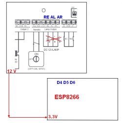
    I'm trying to connect the outputs from the alarm (standby, armed, motion detected) to the ESP8266 (later to HA), but I don't know how to do it due to the different supply voltages. The alarm outputs RE, AL, AR (lights can be connected there) are to be read on ESP inputs D4, D5, D6.
    Alarm has 12v outputs, esp 3.3v how to reconcile this? A divider on resistors alone probably won't be enough, is there any simple way to accommodate this?
    Diagram showing the connection of alarm outputs to ESP8266.

    ESP is fed from the alarm via an inverter.
  • ADVERTISEMENT
  • ADVERTISEMENT
  • #3 20800654
    inot
    Level 37  
    Optocouplers can be connected in place of tubes.
  • #4 20800727
    xury
    Automation specialist
    From the diagram it appears that the outputs from the alarm are OC type. If the inverter and the alarm share a common ground then you can even dispense with opto-isolation or relays Then just pull_up to 3.3V and connect directly to the alarm output.
    There is no 12V on these outputs in the active state they are shorted to ground and in the inactive state they are in high impedance. I have done this more than once.
  • ADVERTISEMENT
  • #5 20800812
    dartek2000
    Level 8  

    The alarm is some age-old model from Conrad.
    Alarm and ESP share a common ground (the alarm feeds into the ESP).
    I was thinking of a pull-up resistor, but I don't quite know how that would behave.
    I measured the voltages on the alarm outputs and normally there is 12V there, and 1.5V when activated. So would 12V go to the ESP input?

    I guess the easiest way to do this would be on optocouplers.
  • ADVERTISEMENT
  • #6 20800828
    inot
    Level 37  
    dartek2000 wrote:
    normally there is 12V there, and 1.5V when activated.
    Without load? Measure that voltage with a load connected (a resistor is sufficient).
  • #7 20800850
    xury
    Automation specialist
    dartek2000 wrote:
    I measured the voltages on the alarm outputs and normally there is 12V there, and 1.5V when activated. So 12V would go to the ESP input?
    How did you measure this voltage? Did you measure between ground and output, or between 12V and output ?
    Of course the output must not be connected to anything then.
  • #8 20803338
    kmarkot
    Level 29  
    I have a 12 V relay connected to my Satel ca-10 under the alarm output
    Additionally, I have used a 2-channel 5V 10A Arduino relay module for arming and disarming
    All connected to HA via ESPHome


    ota:
    switch:
      - platform: gpio
        pin: D1
        name: "Switch 1_1"
        id: switchno11
        interlock: [switchno11]
        inverted: true
        on_turn_on:
        - delay: 1000ms
        - switch.turn_off: switchno11
      - platform: gpio
        pin: D2
        name: "Switch 1_2"
        id: switchno12
        interlock: [switchno12]
        inverted: true
        on_turn_on:
        - delay: 1000ms
        - switch.turn_off: switchno12    
    binary_sensor:
      - platform: gpio
        pin:
          number: D5
          mode: INPUT_PULLUP
        name: "inputD5"
        id: inputd5
        filters:
          - delayed_on: 500ms
          - invert:
      - platform: gpio
        pin:
          number: D6
          mode: INPUT_PULLUP
        name: "inputd6"
        id: inputd6
        filters:
          - delayed_on: 500ms
          - invert:
      - platform: gpio
        pin:
          number: D7
          mode: INPUT_PULLUP
        name: "inputd7"
        id: inputd7
        filters:
          - delayed_on: 500ms
          - invert:
    
    .
  • Topic summary

    The discussion revolves around connecting 12V alarm outputs (standby, armed, motion detected) to the ESP8266, which operates at 3.3V. The user seeks a solution to reconcile the voltage difference, considering the alarm outputs are typically at 12V and drop to 1.5V when activated. Suggestions include using optocouplers for isolation, as well as direct connections if the alarm outputs are open collector (OC) type and share a common ground with the ESP8266. The importance of measuring the output voltage under load is emphasized to ensure safe interfacing with the ESP inputs (D4, D5, D6). Additionally, a user shares their experience with a relay setup connected to a Satel CA-10 alarm system, integrated with Home Assistant via ESPHome.
    Summary generated by the language model.
    ADVERTISEMENT