logo elektroda
logo elektroda
X
logo elektroda

5-Pin Relay Connection Guide: Car Cut-Off Test, Button Setup, Pins 85, 86, 30, 87a, Bulb Wiring

kamilo1409 40797 30
ADVERTISEMENT
Treść została przetłumaczona polish » english Zobacz oryginalną wersję tematu
  • #1 16769092
    kamilo1409
    Level 7  
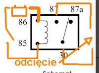
    I have a 5-pin relay as in the picture + a button. I want to cut myself off in the car, but I wanted to do a test run first. I connected the button to pins 85 and 86, pin 30 led to the battery to +, 87a to + in the bulb, and from the bulb - to - on the battery. Unfortunately it does not work. The light bulb stays on all the time. How to connect it properly?
  • ADVERTISEMENT
  • #3 16769115
    kamilo1409
    Level 7  
    The button is as I see further under 85.86, or as a cutoff? Or otherwise? I have something like in the picture and how to connect it?
  • #4 16769140
    marqqv
    Level 32  
    What do you want to cut off? You connect the fuel pump, ignition, etc. to 30 and 87-87a depending on the configuration. So you take a break on the cable you want to cut off and connect to these pins. I don't know what your ideas are, this is one of them. these pins act as if you cut the wire and combined action- combined action doesn't work. 85-86 are the pins from the coil that must have power to change the position of the pins between 87-87a
  • ADVERTISEMENT
  • #5 16769141
    _jta_
    Electronics specialist
    Only the battery is still connected there.
  • #6 16769156
    kamilo1409
    Level 7  
    I thought that if, for example, I want to make a cut-off on the pump, it is a plus, I plug the cut-off cable under 30 and, for example, 87a, and under 85.86 I connect the button and play. But it's not as simple as I thought
  • ADVERTISEMENT
  • #8 16769163
    kamilo1409
    Level 7  
    Now everything is clear. On the "scheme" it is already cut - and can I cut + and connect it the same way? Will it work differently?
  • #9 16769168
    marqqv
    Level 32  
    You can ground minus most of it is on the bodywork.
  • #10 16769174
    kamilo1409
    Level 7  
    Ok, I will test in the morning. I'll ask again tomorrow what and how, but for now, thanks :)
  • #11 16769201
    marqqv
    Level 32  
    Set the relay to "pull" when the motor is running
    The reason for this.
    - battery saving
    -security is at rest when there is no one in the car.
    - a fuse in the power circuit would also be needed.
  • #12 16769209
    kamilo1409
    Level 7  
    I want to make it so that when I turn on the ignition, a certain action will be performed, but when I press the button, it will only switch to the pump and ignition. And as for the fuse, where in the diagram is it best to put it and how durable? Aaa ... well, I will want to take a plus from the ignition switch, so that there is no current on any of these two pins.
  • #13 16769219
    marqqv
    Level 32  
    kamilo1409 wrote:
    And as for the fuse, where in the diagram is it best to put it and how durable?


    On the plus side going to pin 85 or 86, i.e. to the coil, the size of 5A-7.5A is enough.

    And don't put the switch under the gear shift bellows because it's the most popular place. :D

    Solder all connections and check after making if anything heats up or melts.
  • #14 16769356
    kamilo1409
    Level 7  
    I don't know why, but I don't have support when I did according to the scheme. When I press the button it turns on the light, but when I let go it turns off. Of course, from the beginning I meant the button as I wrote, not the switch.
  • ADVERTISEMENT
  • #15 16769376
    ALIBABA I
    Level 33  
    Hello, it looks like you have the wrong button.
  • #17 16769406
    marqqv
    Level 32  
    kamilo1409 wrote:
    it was a button as I wrote, not a switch

    This is not an ordinary relay, but a bistable one in this system, only an ON/OFF switch
  • #18 16769413
    kamilo1409
    Level 7  
    That's what I have;/ what should I use to use the button?
  • #19 16769421
    marqqv
    Level 32  
    kamilo1409 wrote:
    what should i use to use the button?


    E.g. allegro type Bistable relay DIN 12V or 24V FV
  • #20 16769460
    kamilo1409
    Level 7  
    This is the only thing that pops up for me, such home relays. What car relay?
  • #21 16769538
    marqqv
    Level 32  
    kamilo1409 wrote:
    What car relay?


    CAR BISTABLE IMPULSE RELAY 4-WSP also allegro
  • #22 17047625
    pmp3
    Level 10  
    marqqv wrote:
    5-Pin Relay Connection Guide: Car Cut-Off Test, Button Setup, Pins 85, 86, 30, 87a, Bulb Wiring


    Can it Relay 12V 30 - 40A BLOW 0392 connect to a microcontroller or 555 np timer via an npn transistor tip 120 ? How to combine such a set?

    Will the button in the picture be on pins 2 and 3 of the transistor, and pin 86 of the relay connected to pin 1 of the transistor?
  • #23 17047827
    _jta_
    Electronics specialist
    Yes, I am looking for schematics and here is a one-way diode still used? Does she matter?

    The diode is connected in parallel to the relay coil so that breaking the connection does not generate high voltages on the coil. This is especially important if the coil is controlled by a transistor - it can burn out if there is no diode. But also when controlling the button without the diode, the button contacts burn out faster.

    Will the button in the picture be on pins 2 and 3 of the transistor, and pin 86 of the relay connected to pin 1 of the transistor?

    Do not use the terms pin 1/2/3, only emitter/base/collector - someone will look at another catalog note and there may be a different numbering, and besides, the terms are illegible without information about the adopted pin numbering; in this note pin 1 is base, 2 is collector, 3 is emitter.

    Pin 86 of the relay is connected to the +battery - definitely do not connect the base of the NPN transistor to the +supply. But I don't know how to connect it, because you didn't write what you want to achieve, what role this transistor should play, how it should be connected to the microcontroller/555.
  • #24 17048611
    pmp3
    Level 10  
    _jta_ sorry for my unprofessional language, I'll try to use proper terminology next time.
    The project is a stirrer based on: 12v wiper motor; transformer with bridge and relay and pcb with applied 555 system.
    I made an app out of it project I connected the transistor like in this project . For this I want to attach the above. relay. I checked this setup on this one relay And it works. However, I suspect that in the long run something may go wrong in it, because on my cube it is written that the permissible constant voltage is 5v, and the variable voltage is 230v.
  • #25 17049174
    _jta_
    Electronics specialist
    As for the relay, it should be controlled with 5V, but it can switch 10A, 250V/125V alternating voltage, or 30V/28V constant (I don't know what two voltages mean, unless one contact is for a different voltage, and the other to others?). He is still on some electronics board - a diode, a transistor, 3 resistors, 2 LEDs.
  • #27 20158117
    globi.wan
    Level 10  
    I have one question about this relay
    If the circuit 86 85 is open, the relay does not give current at all to either 87 or 87a, and if it is closed, it gives both 87 and 87a?
    Is it simply depending on whether the circuit 86 85 is open or closed, the relay gives current either to 87 or to 87a?
  • #28 20158951
    abart64
    Level 33  
    globi.wan wrote:
    Is it simply depending on whether the circuit 86 85 is open or closed, the relay gives current either to 87 or to 87a?

    Yes. Without power to coil (85 86) 30 is shorted to 87a. When applied, power 30 shorts to 87.
  • #29 20161884
    kp.
    Level 11  
    _jta_ wrote:
    The diode is connected in parallel to the relay coil so that breaking the connection does not generate high voltages on the coil. This is especially important if the coil is controlled by a transistor - it can burn out if there is no diode. But also when controlling the button without the diode, the button contacts burn out faster.


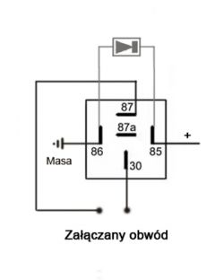
    Hello, taking the opportunity that such a topic was created, I will ask, that is, in any case, regardless of how we use such a relay, whether it's to start some additional halogens, or to cut off the pump, starter or ignition, or everything at once on several relays, then on each relay, such a diode is indicated on the power supply (I understand that rectifying or indifferent) connected with the cathode always to plus, and the anode to minus (as in the picture?) And it will not do any harm, on the contrary, it will be beneficial for the relay?
    5-Pin Relay Connection Guide: Car Cut-Off Test, Button Setup, Pins 85, 86, 30, 87a, Bulb Wiring

    By the way, I will ask again, it is indifferent whether we give + 85 or 86 to the coil?
  • #30 20162079
    Domen4
    Level 19  
    kp. wrote:
    will it be beneficial for the relay?

    It's not about the benefit for the relay, but about the benefit for the power source.
    Due to the inductance of the coil and the sudden power failure, a very high voltage (opposite to the supply voltage) will appear across the coil.

    kp. wrote:
    it is indifferent whether we put + on the output 85 or 86 on the coil?

    It is not indifferent in the case of the mounted diode, which, as a colleague mentioned - must always be connected in the same way.

Topic summary

The discussion revolves around the proper connection of a 5-pin relay for a car cut-off system, specifically addressing issues with wiring a button to control the relay. The user initially connected the button to pins 85 and 86, with pin 30 connected to the battery positive and pin 87a to a light bulb, but the bulb remained on continuously. Responses clarified that pins 30 and 87 (or 87a) should be used to interrupt the circuit of the component being cut off, such as a fuel pump or ignition. It was emphasized that the relay's coil (pins 85 and 86) must be powered to switch between pins 87 and 87a. Suggestions included using a bistable relay for the desired functionality and ensuring proper grounding. The importance of a diode across the relay coil to prevent high voltage spikes was also discussed. The conversation highlighted the need for correct wiring and the potential use of a fuse for safety.
Summary generated by the language model.
ADVERTISEMENT