logo elektroda
logo elektroda
X
logo elektroda

Construction of a migomat or a transformer suitable for a migomat?

napoleon215 8061 16
ADVERTISEMENT
Treść została przetłumaczona polish » english Zobacz oryginalną wersję tematu
  • #1 16839849
    napoleon215
    Level 11  
    Hello
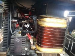
    He plans to make a migomat from a transformer bought from scrap. The question is whether it will be suitable and what welding current will I get the maximum from it?
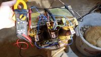
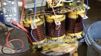
    Construction of a migomat or a transformer suitable for a migomat? Construction of a migomat or a transformer suitable for a migomat? Construction of a migomat or a transformer suitable for a migomat?
  • ADVERTISEMENT
  • #2 16839948
    Anonymous
    Anonymous  
  • ADVERTISEMENT
  • #3 16839953
    arekd555
    Level 16  
    Hello. The transformer is good and it is suitable for a migomat, the voltage on the secondary winding is a bit too high, but you can connect them in a delta because I can see that it is star connected.
  • ADVERTISEMENT
  • #4 16839978
    Anonymous
    Level 1  
  • ADVERTISEMENT
  • #5 16840101
    arekd555
    Level 16  
    I have a question, what is the cross-section of the secondary winding flat bar.
  • #6 16840116
    robokop
    VIP Meritorious for electroda.pl
    Kraniec_Internetów wrote:
    The voltage of a single winding is a bit low, but if you connect them in series (with one winding in out-of-phase), you would create a 3x230V / 1x70V transformer. So almost perfect for welding. The current comes out 53A. The construction of the welding transformer is slightly different, that during welding the voltage drops to about 30V and the current increases a lot. Unfortunately, this transformer is almost certainly not adapted to such work. Not suitable for a welding machine in my opinion, but you can try. In the secondary winding you would have to connect a suitable coil limiting the current and making it difficult to extinguish the arc.

    Dude, please - go away, advise elsewhere. In this system, with a half-wave rectifier, the secondary voltage will be 1.17 RMS phase voltage, with full wave (6 diodes) 2.34 RMS phase voltage (i.e. measured between the end of the winding and the center of the star). When connecting the secondary winding into a delta, the voltage at its ends will be lower by the root of 3 - that is, the phase voltage of 3.7.2V will become about 21V - with a 6-pulse rectifier this will give a voltage of 50V - definitely too much for a migomat. I would stay with the current connection, i.e. star, and make a bridge controlled on 3 thyristors. Theoretically, the alternating voltage of 37V will become more or less the same, or even slightly less, of direct current - to blink just right - you can always capture it by properly controlling thyristors. In addition, a fairly large choke.
    Welding machines without rewinding cannot be made of it - strictly welding transformers are built as dissipation transistors, on the outside they are characterized by a specific way of arranging the windings - primary and secondary one, the coils are wound narrow and tall - figuratively speaking - to move them away from each other and the core .
  • #7 16840245
    napoleon215
    Level 11  
    The flat bar on the secondary is 10x4 mm and the primary wire diameter is 2mm
  • #8 16840924
    stasiekb100
    Level 29  
    Migomat 250 A 30% will easily come out of it, but other elements are needed.
  • #9 16853219
    napoleon215
    Level 11  
    After reading some smart articles, I came to the following conclusions:
    The voltage of the secondary winding is 37.5 volts, so after straightening:
    For a 3-phase system we have:

    U = 1.35Up
    U = 1.35x37.5 = 50.6V A bit too much

    where: Up - RMS value of the line supply voltage

    After switching the secondary winding to delta, the voltage will be:

    U = ?3xUf = 37.5V

    Uf = U / ?3

    Uf = 37.5 / ?3 = 37.5 / 1.73 = 21.6V

    After straightening

    U = 1.35xUf = 1.35x21.6 = 29.6V

    Let's assume 30V for a migrate already approx.

    Now the electricity:

    P = UxI
    I = P / U = 4000/30 = 133A

    It is the rated current of the transformer, i.e. the current that can be loaded up to 40 ° C without forced cooling (without fan)
    With an additional fan, the current can be increased (to what value I will specify during the tests when the welder is ready)
    It is the current at 100% of the welding machine's work cycle (non-stop welding)
    With a 60% or 35% duty cycle, the current can be analogically increased.

    All data above are my theoretical calculations (not necessarily correct)
    Any comments for and against are welcome.
  • #10 16853254
    robokop
    VIP Meritorious for electroda.pl
    You have a mistake in this calculation. With a delta connection and a 6 diode rectifier, you will have 2.34 of the phase voltage, i.e. phase-to-phase in this case - 2.34x (37.5 / ?3 = 37.5 / 1.73 = 21.6V) = 50.3V.
  • #11 16853317
    Akrzy74
    Rest in Peace
    napoleon215 wrote:
    The question is whether it will be suitable and what welding current will I get the maximum from it?
    When someone has the soul of a constructor and passionately wants to do something for himself (or others) like Mr. Adam Klimek - is well-read on a given topic and prepared, he should properly describe everything in the first post.
    So please write what is the expected current of this transformer, what voltage and in what connection system. What is / will be the way of regulation, conclusions drawn from the topic Link
  • #12 16853531
    napoleon215
    Level 11  
    ] I have not read the subject, so I asked others what their opinion was on this subject. After familiarizing myself with the topic, I wrote some observations in the previous post. It describes the current expected in delta connection. Of course, regulation of thyristors.

    I just checked the theories in practice.
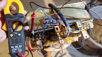
    In the pictures below, provisional delta connection of the transformer and voltage after straightening (of course, the wires and rectifiers are only temporary for testing)

    Construction of a migomat or a transformer suitable for a migomat? Construction of a migomat or a transformer suitable for a migomat? Construction of a migomat or a transformer suitable for a migomat?
  • #13 16853651
    arekd555
    Level 16  
    Hello. In such a connection of the secondary winding, the voltage has a good value for building a migomat. I propose to build a half-controlled bridge for this transformer and it will be ... ok ... please remember about the choke behind the bridge.
    I also built a migomat on a similar luck with very similar voltages and it's great.
    I have a voltage regulation from 15 V to 30 .... greetings.
  • #14 16853671
    robokop
    VIP Meritorious for electroda.pl
    Apparently just right, but once - it is the no-load voltage, you should expect a decrease at load, and two additional ones will drop when using thyristors - even to 1.6V on each of them. In any case, after adding the appropriate gland, you will be welding - you will only need to combine the gland with taps for proper regulation in the entire range.
  • #15 16853702
    arekd555
    Level 16  
    Even this voltage drop will not hurt for welding with 1.2 mm wire. The choke does not have to be with taps and much smaller than in a single-phase semi-controlled bridge.
  • #16 16853779
    robokop
    VIP Meritorious for electroda.pl
    arekd555 wrote:
    Even this voltage drop will not hurt when welding with 1.2 mm wire.

    I wouldn't rush with 1.2 - 0.8 is much more universal and will melt it deeper.
    Quote:

    The choke does not have to be with taps and is much smaller than in a single-phase semi-controlled bridge.
    Do something once and for all and make sense. In the case of a single-phase device, a choke is required to keep the current flowing, as the waveform periodically drops to zero - with a controlled rectifier and these zero-drop periods are longer - the arc goes out and ignites, causing splash etc. effects - in other words you can't weld.
    In the case of a three-phase rectifier, a non-extinguishing waveform is obtained when using a rectifier bridge - it does not drop to zero at any time, it remains around the average value. Redundant or small choke for minimal smoothing of the current wave. In the case of a three-phase controlled rectifier, the current pulsation is greater - although the waveform does not drop to zero, but the current pulsates - a choke with a higher inductance will store energy to compensate for the average current value. Too large a choke will cause an undesirable "softening" of the "source" for the high current range See professional large migomats - you have either an adjustable inductance or multiple ground lead sockets for different current ranges, although you can always try transducer methods.
  • #17 17682578
    napoleon215
    Level 11  
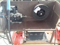
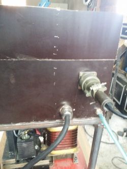
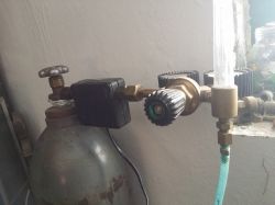
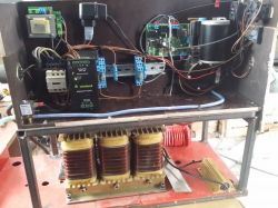
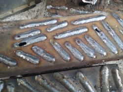
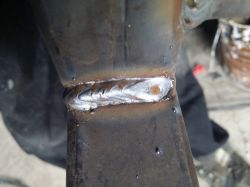
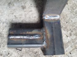
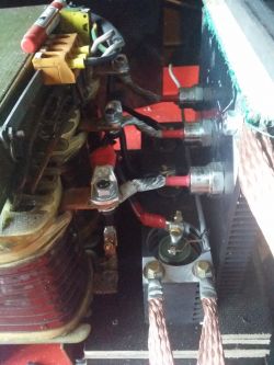
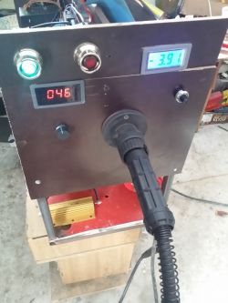
    Migomat is almost finished, there is still cooling and casing (at current temperature -3 there is no need for heat sinks and transformer are lukewarm after long welding). With a 0.8 wire, the max current is 150A and with 1.0 230A I don't have a 1.2 wire. The voltage during welding at 230A is 28v at 150A 26vA at 100A 24v.

    https://www.youtube.com/watch?v=FAaxBuvQvE8

    Construction of a migomat or a transformer suitable for a migomat? Construction of a migomat or a transformer suitable for a migomat? Construction of a migomat or a transformer suitable for a migomat? Construction of a migomat or a transformer suitable for a migomat? Construction of a migomat or a transformer suitable for a migomat? Construction of a migomat or a transformer suitable for a migomat? Construction of a migomat or a transformer suitable for a migomat? Construction of a migomat or a transformer suitable for a migomat? Construction of a migomat or a transformer suitable for a migomat? Construction of a migomat or a transformer suitable for a migomat? Construction of a migomat or a transformer suitable for a migomat?

Topic summary

The discussion revolves around the feasibility of constructing a MIG welder (migomat) using a transformer sourced from scrap. Participants evaluate the transformer's specifications, noting that while it can be adapted for MIG welding, the voltage and current characteristics may require adjustments. The transformer, rated at 4kVA, presents challenges due to its high secondary voltage, which can be mitigated by connecting the windings in delta configuration. Calculations suggest that the transformer can deliver a maximum current of approximately 133A under optimal conditions, with voltage adjustments necessary for effective welding. The importance of incorporating a choke for current stabilization and the potential need for additional components for regulation are emphasized. Users share practical experiences and modifications made to similar setups, indicating successful outcomes with proper adjustments.
Summary generated by the language model.
ADVERTISEMENT