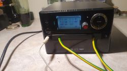
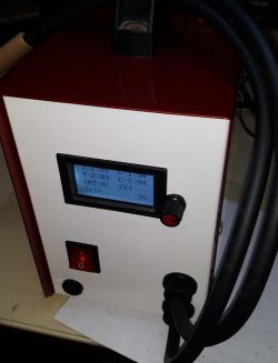
Interesting design - the assumption to fill the cross-section with a copper flat bar instead of the earth wire raises the filling by a good 20%, i.e. the magnetic flux of the core induces a greater current on the winding.
I myself 900 W cores (700 W skipping) wind 6 cores. grounding wire 25 mm2, packing it very tightly, practically pressed on a square (on wd40

I think that an interesting modification going further in this direction would be to wind the winding with a copper flat bar with a square cross-section, as in a transformer soldering iron.
Minor disadvantages I notice:
- the coil is made of several sheets, yes, touching each other, but with such currents, shouldn't they be more of a monolith? I know, it is used to wind the coils with several wires, but when we fight for every amp ...

- a colleague cut the core to mount the winding. OK, I'm assuming flex. Now, in order for the magnetic flux in the core to be as high as possible, it would be optimal to weld / weld the core. Every bit of air on the contact surface of the cut-out exponentially increases the magnetic field losses, i.e. the efficiency of the transformer.
But summing up the profits and losses, I think that the device made in this way has a higher efficiency than the Sunkko 797 - for comparison, it uses a 700 W core and a 16mm2 wire winding.
Question to a colleague:
What is the cross section of a single sheet coil and how many rolls are there?
Ps: in my 900 W set with the same programmer, the welding parameters:
0.12 mm steel-nickel plate - t1 = 08 I1 = 67 t2 = 05 i2 = 20
Steel-nickel plate 0.2 0mm - t1 = 10 i1 = 80 t2 = 05 i2 = 20
With a thinner plate, it even applies a single pulse, which is sufficient.


