logo elektroda
logo elektroda
X
logo elektroda

Converting ATX Power Supply for Workshop: Diode Resistors, Parallel Connections & 12V Line Load

mathun 6423 16
ADVERTISEMENT
Treść została przetłumaczona polish » english Zobacz oryginalną wersję tematu
  • #1 16864991
    mathun
    Level 8  
    Hi!
    I am at the stage of converting the ATX power supply into a workshop.
    There are many instructions on the Internet, but I don't understand everything. Therefore, I have a few questions for you.


    1. The diodes in my project are powered by 5V line. I know what resistors I should match when it comes to the Ohm parameter, but I don't really know what about W. On websites, everyone explains how to make a good resistor by matching the ohm value. Is a 0.25W resistor enough for a 5W line, or maybe 0.5W ... or maybe it must be 5W?

    2. How do I connect 2 0.25W resistors in parallel, I will have 0.5W? Is that how it works?

    3. With relatively new ATX power supplies, it is said that the + 12V line must be artificially loaded to a minimum of 22 Ohm for the power supply to work stably. I also read that in this case you should use resistors of at least 10W. Is it true? Is it possible to somehow use 5W resistors so that they do not burn? I have already asked in 5 local stores and the largest resistors they have are 5W.
    Or maybe in my case it is enough to load the + 5V line?

    4. It's also nice if someone was able to recommend me a good book, some basics of electronics (but written in such a way that the child understands, because in this area not everything is easily absorbed for me).
  • ADVERTISEMENT
  • ADVERTISEMENT
  • #3 16865027
    zster

    Level 28  
    1) How do you calculate DC current power? I * V ..... you choose the resistor power with reserve to the obtained result.

    2) It depends on the resistance value of these resistors. These values must be perfectly the same so that each has the same power. But in simple terms, yes, this is how it works.

    3) Similar to the first point. Given the voltage and resistance, you calculate the current. Given the current and voltage, you calculate the power and select resistors in reserve.

    4) There is so much that everyone will recommend something different ...
  • #4 16865191
    mathun
    Level 8  
    helazbyś wrote:
    You can find answers to some of your questions at this link
    https://majsterkowo.pl/zasilacz-warsztatowy-ze-starego-zasilacza-atx/

    I won't find answers to these questions here. I have been to this site before.

    zster wrote:
    1) How do you calculate DC current power? I * V ..... you choose the resistor power with reserve to the obtained result.
    3) Similar to the first point. Given the voltage and resistance, you calculate the current. Given the current and voltage, you calculate the power and select resistors in reserve.

    It's black magic to me.
    Could you show me how this is calculated with an example?
    a) I want to connect the diode to e.g. + 5V 2A, I found out that the resistor should be 300 Ohm, how many "W" is enough?
    b) I want to artificially load the + 12V 17A line with a 22 Ohm resistor
  • Helpful post
    #5 16865272
    _jta_
    Electronics specialist
    12V ^ 2 / 22? = 6.55W; but you can take, for example, 2 resistors 43? / 5W connected in parallel (each will have 12V ^ 2 / 43? = 3.35W), or 3 resistors 68? / 3W ...

    Do you want to power high-power LEDs from it? But how did you get 300??
  • #6 16865350
    mathun
    Level 8  
    _jta_ wrote:
    12V ^ 2 / 22? = 6.55W; but you can take, for example, 2 resistors 43? / 5W connected in parallel (each will have 12V ^ 2 / 43? = 3.35W), or 3 resistors 68? / 3W ...

    Do you want to power high-power LEDs from it? But how did you get 300??


    I don't know how I calculated it. That's what I have in my notes. Now as I use the calculator
    for the green diode I get 100 Ohm
    (Green LED Uf = 3.1V, If = 20mA,)
    and for the red diode (Uf = 2.03V, If = 20mA,) 148.5?
    hmm can you give more resistance without side effects? because in total I have soldered to green instead of 100 I have 220, and with red instead of 150 I have 300. They shine well :)

    as for these artificial load resistors, it means that I can safely use 5W in parallel? even if I needed 20W (e.g. 4x5W in parallel)?

    Thank you for your understanding
  • ADVERTISEMENT
  • Helpful post
    #7 16866183
    zster

    Level 28  
    mathun wrote:
    hmm can you give more resistance without side effects?


    Of course you can. 20mA is the upper limit of the current for this diode, but it can be powered and 10mA and it will shine well.

    mathun wrote:
    does it mean that I can use 5W in parallel? even if I needed 20W (e.g. 4x5W in parallel)?


    You can. You can also experimentally check whether the power supply will turn on at higher load resistances. The greater the resistance, the less power goes to "heating the resistors".
  • #8 16866423
    _jta_
    Electronics specialist
    ATX power supply usually has a power counted in hundreds of W (however there are also smaller ones, e.g. 90W for computers in Small Factor housing) - do you have enough LEDs for power supply that you need such power? If so, then maybe it is worth thinking about how to better manage it - for example, make a current source powered from 12V, and connect a pair of LEDs in series so that over 80% of the power taken from the power supply goes to power the LEDs, not heating the resistors serial.
  • #9 16866712
    mathun
    Level 8  
    _jta_ wrote:
    Do you have enough LEDs for power supply that you need that much power?

    This is to be a workshop power supply. LEDs, i.e. in Polish, the LEDs are in my project only to make them shine nicely 1. The red LED is to indicate that it is connected to the network, 2. the green LED that it is running / ready to work. This is just such a good thing, and the power supply itself will not be used to power other LEDs than those in the housing.
  • #10 16866982
    _jta_
    Electronics specialist
    The + 5V 2A output is probably Stand-By, so the voltage is there even with the power supply turned off (or rather its main part is turned off), so it may be possible to adjust the voltage for the main part and keep the + 5V to power the LEDs.
  • #11 16876843
    mathun
    Level 8  
    I don't want to play regolation. Not yet. I also have a second power supply. If it goes well, maybe I will do another one with regulation.

    Further questions:

    I have 6 yellow + 12V cables, how many should I connect the artificial load to and how many should I leave? I have 11 wires at my disposal for grounding.
    I have a set of 3 resistors connected in parallel 68 Ohm 5W.

    update
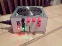
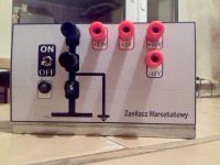
    The power supply is ready. I just don't know why
    at + 3.3V it is 3.46V
    at + 5V it is 5.46V
    at + 12V it is 11.08V
    and at -12V it is only -10.29V

    Converting ATX Power Supply for Workshop: Diode Resistors, Parallel Connections & 12V Line Load Converting ATX Power Supply for Workshop: Diode Resistors, Parallel Connections & 12V Line Load


    Update 3

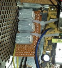
    Everything is fine. I connected two + 12V lines to 3 68 Ohm resistors. I equipped the resistors with heat sinks. Nevertheless, with the power supply turned on empty, the resistors get hot. You can touch it, but not longer than a few seconds because they burn. Converting ATX Power Supply for Workshop: Diode Resistors, Parallel Connections & 12V Line Load
  • #12 17586880
    Skipperab kobieta
    Level 10  
    What is the power rating of those resistors that get hot?
  • #13 17590536
    helazbyś
    Level 16  
    ,, I have a set of 3 resistors connected in parallel 68 Ohm 5W. ''
  • ADVERTISEMENT
  • #14 17590787
    Skipperab kobieta
    Level 10  
    Maybe the power you give off on these resistors is greater than their rated power and therefore they heat up?
  • #15 17591429
    _jta_
    Electronics specialist
    There is 12V, and to achieve a power of 5W on a 68? resistor, you need over 18V - at 12V it will be 2.1W.
  • #16 17592080
    jarek_lnx
    Level 43  
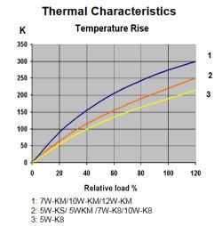
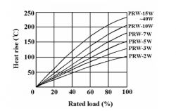
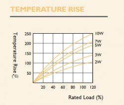
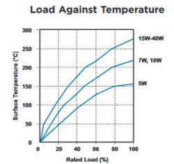
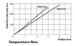
    The resistors heat up because this is their role, they dissipate power in the form of heat, in the case of wire in ceramic housings, these are temperature-resistant elements and it would be a pity not to use it ;) They are designed so that at nominal power the surface temperature can reach from 150 ° C to 300 ° C depending on the model and manufacturer, the smaller the heat dissipation area and the higher the power, the higher the temperature. While the resistor itself could work at such high temperatures, it would rather not be in the vicinity of other elements or the laminate, which means that PCBs usually have to limit the power loss below half the nominal value, and you can get burned anyway.

    Below are some examples from the datasheet
    Converting ATX Power Supply for Workshop: Diode Resistors, Parallel Connections & 12V Line Load Converting ATX Power Supply for Workshop: Diode Resistors, Parallel Connections & 12V Line Load Converting ATX Power Supply for Workshop: Diode Resistors, Parallel Connections & 12V Line Load Converting ATX Power Supply for Workshop: Diode Resistors, Parallel Connections & 12V Line Load
    Converting ATX Power Supply for Workshop: Diode Resistors, Parallel Connections & 12V Line Load
  • #17 17592500
    Skipperab kobieta
    Level 10  
    Thanks, I'm just learning the basics of electronics and such knowledge will definitely be useful to me.

Topic summary

The discussion revolves around converting an ATX power supply for workshop use, focusing on the appropriate selection of resistors and diodes for stable operation. Key questions include determining the correct wattage for resistors connected to a 5V line, the method for connecting resistors in parallel, and the necessity of loading the +12V line with a minimum resistance for stable power supply operation. Users share calculations for resistor values and wattage, emphasizing the importance of using resistors with sufficient power ratings to prevent overheating. The conversation also touches on the use of LEDs for indication purposes and the implications of using multiple resistors in parallel to achieve desired power ratings.
Summary generated by the language model.
ADVERTISEMENT