Hello,
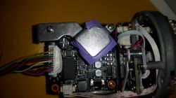
Gentlemen, I am looking for a distribution of power and signal pins that are plugged into the ankle inside the BCS-TIP1130IR camera.
I have such a camera, but I do not have the original cable / connector for it, which was terminated inside the camera with a 12-pin connector and outside with a power plug and RJ45 socket.
I will be grateful for the description of where and how to connect so that the camera moves.
[Edit]
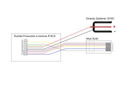
In connection with the solution of the problem I put a diagram of pins connection in the IP camera and their connections to the RJ45 and to the power socket.

Below is a brief description of the connections between the cube in the camera and RJ45 and the power socket according to the diagram shown:
K1 - contact not connected in camera (Has connection with K2)
K2 - yellow wire in the camera - Pin No. 4 or 5 in RJ45 - Plus PoE supply (Note: PoE supply is 48VDC)
K3 - a contact not connected in the camera (It has an internal connection with K4)
K4 - gray wire - Pin No. 7 or 8 in RJ45 - PoE supply minus (Note: PoE supply is 48VDC)
K5 - green wire (no info)
K6 - red wire - plus 12V DC power supply
K7 - white wire (no info)
K8 - black wire - minus 12VDC power supply
K9 - brown wire - Pin No. 1 in RJ45
K10 - purple wire - Pin No. 2 in RJ45
K11 - orange wire - Pin No. 3 in RJ45
K12 - blue wire - Pin No. 6 in RJ45
In case someone has only damaged the RJ45 socket end and connects it to the UTP cable, the relationship looks like this:
Camera -------- UTP
brown - white-orange
purple - orange
orange - white-green
yellow - blue and / or white and blue
blue - green
gray - white brown and / or brown
I also attach a diagram in the form of a file .
Special thanks to @ maly_13 for helping me solve the problem.
Gentlemen, I am looking for a distribution of power and signal pins that are plugged into the ankle inside the BCS-TIP1130IR camera.
I have such a camera, but I do not have the original cable / connector for it, which was terminated inside the camera with a 12-pin connector and outside with a power plug and RJ45 socket.
I will be grateful for the description of where and how to connect so that the camera moves.
[Edit]
In connection with the solution of the problem I put a diagram of pins connection in the IP camera and their connections to the RJ45 and to the power socket.

Below is a brief description of the connections between the cube in the camera and RJ45 and the power socket according to the diagram shown:
K1 - contact not connected in camera (Has connection with K2)
K2 - yellow wire in the camera - Pin No. 4 or 5 in RJ45 - Plus PoE supply (Note: PoE supply is 48VDC)
K3 - a contact not connected in the camera (It has an internal connection with K4)
K4 - gray wire - Pin No. 7 or 8 in RJ45 - PoE supply minus (Note: PoE supply is 48VDC)
K5 - green wire (no info)
K6 - red wire - plus 12V DC power supply
K7 - white wire (no info)
K8 - black wire - minus 12VDC power supply
K9 - brown wire - Pin No. 1 in RJ45
K10 - purple wire - Pin No. 2 in RJ45
K11 - orange wire - Pin No. 3 in RJ45
K12 - blue wire - Pin No. 6 in RJ45
In case someone has only damaged the RJ45 socket end and connects it to the UTP cable, the relationship looks like this:
Camera -------- UTP
brown - white-orange
purple - orange
orange - white-green
yellow - blue and / or white and blue
blue - green
gray - white brown and / or brown
I also attach a diagram in the form of a file .
Special thanks to @ maly_13 for helping me solve the problem.


