logo elektroda
logo elektroda
X
logo elektroda

Calculating Apparent, Reactive, and Active Power for Receiver with I=5A, Pn=1000W, Un=230V

Hold_on1 27813 41
ADVERTISEMENT
Treść została przetłumaczona polish » english Zobacz oryginalną wersję tematu
  • #31 17054360
    kozi966
    Moderator of Electricians group
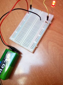
    I asked for a resistor, not a photo of the package ... if someone put 100 ohm resistors in the package by chance, then what?

    By the way, show us how you assembled this circuit. Maybe you made a diode short?
  • ADVERTISEMENT
  • #32 17054385
    Hold_on1
    Level 6  
    All in all, right, here is the photo, although on the Internet I found the specifications of this diode and write there Working parameters:
    Current If: 20mA
    Voltage Vf: 2.0 - 2.3 V
  • #33 17054391
    kozi966
    Moderator of Electricians group
    The barcode resistor is 1kom +/- 10% (measure this with a meter).
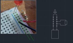
    So now show us how you connected it:
    You made a diode short.
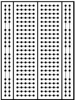
    These lines along are one common wire.

    The contact plate looks like this (the longitudinal lines are galvanically connected to each other):
    Calculating Apparent, Reactive, and Active Power for Receiver with I=5A, Pn=1000W, Un=230V
  • ADVERTISEMENT
  • #34 17054416
    Hold_on1
    Level 6  
    I do not understand why there was a short circuit, the current flowed through the entire resistor and flowed from the diode from the ground?
  • #35 17054429
    kozi966
    Moderator of Electricians group
    It is easier to explain:
    The resistor is short-circuited in these inputs, and the diode short-circuits + and - from the battery.

    Calculating Apparent, Reactive, and Active Power for Receiver with I=5A, Pn=1000W, Un=230V
  • ADVERTISEMENT
  • #36 17054437
    Hold_on1
    Level 6  
    Could you please show me the correct connection? I would be really grateful
  • ADVERTISEMENT
  • #37 17054439
    DiZMar
    Level 43  
    The diode got full 9V and it had no right to survive. :wink:
  • #39 17054452
    DiZMar
    Level 43  
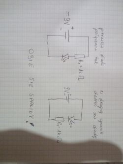
    As you have drawn on the diagram:
    Hold_on1 wrote:
    ...
    Calculating Apparent, Reactive, and Active Power for Receiver with I=5A, Pn=1000W, Un=230V
    ...

    Connect with wires as using a tile is difficult for you.
  • #40 17054476
    kozi966
    Moderator of Electricians group
    DiZMar wrote:
    Connect with wires as using a tile is difficult for you.

    It's probably difficult to understand how the contact plate works :)

    Skip the PCB first and connect these elements without the PCB. Then take the meter and check in what combinations on the board you have a short circuit and try to understand it according to my post # 33.
  • #41 17055727
    Hold_on1
    Level 6  
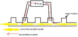
    Okay, sat down a bit today and figured it out. So in my connection (because the current always flows with the smallest resistance line), the current flowed from the positive to the diode, neglecting the resistor (the current flowed after the galvanic connection in the board, instead of the resistor). So it turns out that I tatted the diode with horrendously high intensity. Here is a "diagram" of how the current actually flowed and a picture of the correct connection.
    Calculating Apparent, Reactive, and Active Power for Receiver with I=5A, Pn=1000W, Un=230V Calculating Apparent, Reactive, and Active Power for Receiver with I=5A, Pn=1000W, Un=230V
  • #42 17055774
    kozi966
    Moderator of Electricians group
    Hold_on1 wrote:
    line of resistance

    The line of least resistance.
    Hold_on1 wrote:
    the current flowed through the galvanic connection in the board, instead of the resistor

    You start to use pretty vocabulary, but a galvanic connection is nothing more than a metallic connection. I guess you still don't know why.
    And it is not entirely true that the current flows only along one path, because the current is appropriately divided into individual sections.
    It flows as you thought, but in this case it is in the branch with a resistor ("red") that flows VERY, very, very small current, incomparably smaller to the branch, let's call it "yellow".

    Hold_on1 wrote:
    So it turns out that I tatted the diode with horrendously high intensity. Here is a "diagram" of how the current actually flowed and a picture of the correct connection.

    All of you have already written it and know it, diagrams are unnecessary for us :) .

Topic summary

The discussion revolves around calculating apparent, reactive, and active power for a receiver with a current of 5A, rated power of 1000W, and rated voltage of 230V. The apparent power (S) is calculated as S = U * I, resulting in 1150 VA. The active power is confirmed as 1000W, leading to a reactive power (Q) calculation of Q = S - P = 1150 VA - 1000 W = 150 var. Participants debate the definitions and implications of rated power, the conditions affecting power calculations, and the importance of understanding the power triangle in AC circuits. There are also discussions about the nature of the voltage (AC or DC) and the implications of using incorrect circuit diagrams. The conversation highlights the need for clarity in electrical tasks and the significance of accurate calculations in practical applications.
Summary generated by the language model.
ADVERTISEMENT