logo elektroda
logo elektroda
X
logo elektroda

Calculating Apparent, Reactive, and Active Power for Receiver with I=5A, Pn=1000W, Un=230V

Hold_on1 27813 41
ADVERTISEMENT
Treść została przetłumaczona polish » english Zobacz oryginalną wersję tematu
  • #1 17042127
    Hold_on1
    Level 6  
    Hello,
    As I do not have any electrician I know to help me, I am asking you, dear colleagues, to check the task.

    A current I = 5 A flows through the receiver with the rated power Pn = 1000 W and the rated voltage Un = 230 V. Calculate the apparent and reactive power dissipated in this receiver.

    I read on the Internet that the apparent power is the maximum value of the current (i.e. the one with which the device is able to work without damage, but only for a short moment, a fraction of a second), it is said that it is the product of the RMS voltage and current intensity, so S = U * I

    S = 230V * 5A = 1150 VA
    so the apparent power is 1150 VA and the effective power is 1000W

    However, the reactive power is said to be the difference between these two powers, so:
    Q = 1150 VA - 1000 W = 150
  • ADVERTISEMENT
  • #2 17042469
    DiZMar
    Level 43  
    The rated power has nothing to do with apparent, reactive or active power under specific operating conditions.
    Read the rest on the web.
  • #3 17043705
    Hold_on1
    Level 6  
    Edited the topic, maybe it's okay now, will someone have a look?

    DiZMar - on the Internet I found information that the rated power is active power (i.e. the one that is converted by the device into a different type of energy, e.g. kinetic)
  • ADVERTISEMENT
  • #4 17043719
    DiZMar
    Level 43  
    Hold_on1 wrote:
    ...
    DiZMar - on the Internet I found information that the rated power is active power (i.e. the one that is converted by the device into a different type of energy, e.g. kinetic)

    You have not read it carefully. Rated power is the power with which the device can operate under rated conditions (typical for a given device). The power at a given moment depends on the conditions in which it actually works, which are not necessarily rated. In the case of electrical devices, the main condition is the supply voltage, but also other conditions, such as ambient temperature, etc. Hence, the rated power does not matter for the calculations in the given conditions.

    Added after 9 [minutes]:

    In your case, as you can see, the real power is 1150W, which is 15% more than the rated power, which may damage the device. On the other hand, with a rated voltage of 230V, a current of 4.35A should flow, not 5A. The task is contradictory in itself.
  • #5 17043750
    jack63
    Level 43  
    I do not know what the original content of the task looks like, so it is difficult to judge honestly, but I suspect it lacks information about the shape of the Un voltage. The fact that it is 230V (it is not known whether DC or AC) does not determine its shape at all.
    This task only makes sense for periodic voltage and current. However, it is possible to calculate only assuming a sinusoidal (!) Voltage and current waveform.
    Treat powers like vectors, though they're not, and add them geometrically. You have a power triangle. Read the rest.
  • #6 17044269
    telecaster1951
    VIP Meritorious for electroda.pl
    Gentlemen, please ...
    jack63 wrote:
    it lacks information about the shape of the Un voltage. The fact that it is 230V (it is not known whether DC or AC) does not determine its shape at all.
    What mushroom such texts for? Maybe you still tell the guy to calculate the integral for the effective value?
    DiZMar wrote:
    The rated power has nothing to do with apparent, reactive or active power under specific operating conditions.
    Great, brilliant, we know. This is one common school assignment.
    DiZMar wrote:
    On the other hand, with a rated voltage of 230V, a current of 4.35A should flow, not 5A.
    Cool, cool. I understand that when I give students a problem where 10 amps flow through a 2 ohm resistor, I should be accused of trying to arson. A school assignment does not have to be correctEven it should be abstract.

    This is the entire content of the quest?
  • ADVERTISEMENT
  • #7 17044290
    DiZMar
    Level 43  
    Hold_on1 wrote:
    ...
    On the other hand, the reactive power is said to be the difference between these two powers, so
    Q = 1150 VA - 1000 W = 150
  • #8 17049215
    Hold_on1
    Level 6  
    DiZMar - I know what the names of the individual mathematical operations are, I just "skimmed", I meant the difference VA - W. And instead of answering a short question and specifying the unit, you smeared me a few lines of criticism ...

    This is the whole content of the task, I added a screen of the task to the first post ^^

    PS This is not homework, but I learn electrics "on my own" from the Internet because I consider it an interesting and PRACTICAL direction (my friend has the engine controller in the car, he undressed, he soldered something and works - if he sent PLN 500 to the site, not his, and the driver used is at least PLN 350 and it is not sure how much it will work. :) .
  • Helpful post
    #9 17049576
    kozi966
    Moderator of Electricians group
    Hold_on1 wrote:
    so the apparent power is 1150 VA and the effective power is 1000W

    That's right.
    Hold_on1 wrote:
    Q = 1150 VA - 1000 W = 150

    This is not correct. The formula for calculating the individual powers is a quadratic relationship.
    Hold_on1 wrote:
    in what unit is this power expressed if we subtract VA - W?

    var - reactive volt-amp (lowercase).
  • Helpful post
    #10 17049586
    telecaster1951
    VIP Meritorious for electroda.pl
    There is only one way to solve this task.
    We consider the rated power as active power. The product of the effective values is the apparent power. Find the formula for reactive power yourself.
  • #11 17049650
    jack63
    Level 43  
    kozi966 wrote:
    The formula for calculating the individual powers is a quadratic relationship.

    After all, I wrote to the author of the topic about the power triangle.
    I don't think he gets what all the helpers are about.
    telecaster1951 wrote:
    jack63 wrote:
    it lacks information on the shape of the voltage Un. The fact that it is 230V (it is not known whether DC or AC) does not determine its shape at all.
    What mushroom such texts for? Maybe you tell the guy to calculate the integral for the effective value?

    And for what mushroom do you write about integration?
    I didn't write a word about him ...
    The task is sloppy and must be guesswork. But what for? Is adding AC to 230V or climbs about the home network / LV a sin?
  • #12 17050029
    telecaster1951
    VIP Meritorious for electroda.pl
    jack63 wrote:

    The task is formulated very nicely and you have to be guessing. But what for? Is adding AC to 230V or climbing a home network / LV a sin?
    And is it the author's fault that such a task is? As someone writes about 230V in a school task, it is a network by default. Don't look for a hole all over.
  • #13 17051233
    Hold_on1
    Level 6  
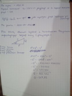
    As indicated by telecaster1951, I tried to solve the task again, this time using the above-mentioned power triangle. The result was really big, 567.89 var, okay?

    Calculating Apparent, Reactive, and Active Power for Receiver with I=5A, Pn=1000W, Un=230V
  • #14 17051455
    telecaster1951
    VIP Meritorious for electroda.pl
    Hold_on1 wrote:
    The result was really big, 567.89 VA, okay?
    Since when is reactive power in VA?
  • #15 17051478
    Hold_on1
    Level 6  
    active power in W.
    apparent power in VA
    reactive power in var
    already corrected, besides solved well?
  • ADVERTISEMENT
  • #16 17051651
    jack63
    Level 43  
    Yes. Now imagine what is the substitute diagram of the receiver. Such an exercise for understanding. :D
  • #17 17051760
    Hold_on1
    Level 6  
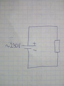
    Under the term "substitute diagram" is an ordinary drawing? Is it something like that?
    Calculating Apparent, Reactive, and Active Power for Receiver with I=5A, Pn=1000W, Un=230V
  • #18 17051865
    jack63
    Level 43  
    Not really. You have a contradiction in the descriptions of the source. On
    resistance gives off only active power, so .... where is the calculated reactive ???
  • #19 17052592
    Hold_on1
    Level 6  
    So I understand that the calculations are good and the diagram is wrong.
    What contradiction do you mean?
    "Only active power is emitted on the resistance, so ... where is the calculated reactive power ???" - how to draw this reactive power, I don't understand anything, someone will explain to me?
  • #20 17052814
    jack63
    Level 43  
    Hold_on1 wrote:
    So I understand that the calculations are good and the diagram is wrong.

    Yes. You have drawn a DC voltage source (battery symbol) with +, - and next to it you have written:
    ~ 230, suggesting an alternating voltage. One contradicts the other.
    Hold_on1 wrote:
    how to draw these reactive power, I don't understand anything, someone will explain to me?

    The power cannot be drawn on the schematic diagram! Items are placed on it. who can "give" or "take" this power. An ideal resistor, as it is in the diagram, "takes" active power, that is, the product of the effective values of current and voltage, when their waveforms are in phase!
    Read what causes reactive power and what elements "generate" it.
  • #21 17053419
    Hold_on1
    Level 6  
    jack63 wrote:
    ... The ideal resistor, as it is in the diagram, "takes" active power ...
    Read what causes reactive power and what elements of self "generate".


    1. What is an ideal source of energy, that is, there is no own resistance (e.g. in a battery), but what is an ideal resistor?
    I read somewhere that the resistors are made with a certain accuracy of 1-5% of their value, i.e. a 1k ohm resistor can actually be ABOUT 1000 ohms +/- 1-5%
  • #22 17053480
    kozi966
    Moderator of Electricians group
    jack63 wrote:
    Perfect resistor, and this is the diagram,

    I see an indefinite element in the diagram. It may well be Z (impedance).
    The author made the mistake of drawing a source of direct voltage, not alternating voltage. Hence the interpretation that it is resistance.
    Hold_on1 wrote:
    After all, the product of effective power and voltage is the apparent power

    It was probably about instantaneous values for which the sign is the same - specifically the product of these values.
    Here is the explanatory topic (picture): https://www.elektroda.pl/rtvforum/topic2601907.html

    Hold_on1 wrote:
    but what is an ideal resistor?

    One that has no inductance and no capacitance. An actual resistor is typically a wound element (like a coil) that has inductance and (interturn) capacitance.

    Hold_on1 wrote:
    ohms

    Not ohms, just talk. Same for volts, amps, and watts.

    Hold_on1 wrote:
    What is this element because I have no idea?

    Coil / capacitor. If you mark the current element with equivalent impedance, it will not be missing.
  • #23 17053547
    Hold_on1
    Level 6  
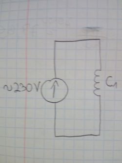
    Thanks for the answer, now is a good drawing?
    Calculating Apparent, Reactive, and Active Power for Receiver with I=5A, Pn=1000W, Un=230V
  • #24 17053706
    jack63
    Level 43  
    Unfortunately not. First of all, we mark the inductance, that is the coil around the world with the letter "L", and the capacitor "C".
    Secondly, an ideal inductive element only consumes reactive power, i.e. it basically shifts the current relative to the voltage in phase by a quarter of a period.
    There must be two basic elements connected to the voltage source.
  • #25 17053712
    kozi966
    Moderator of Electricians group
    Better, but it's not C1 a L1.
    For this you need to know data such as the frequency of the supply voltage expressed in hertz, the inductance of the element expressed in henry and possibly the resistance of the element (if it is not ideal) to calculate the impedance and then the powers.
  • #26 17053894
    Hold_on1
    Level 6  
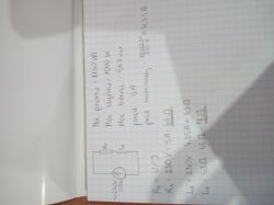
    I also tried to calculate the impedance (because I understand that resistance = direct current, impedance = alternating), assuming that we have an ideal voltage source and the cables connecting the source to the receivers do not constitute any resistance.
    Calculating Apparent, Reactive, and Active Power for Receiver with I=5A, Pn=1000W, Un=230V

    Unless the coil impedance is counted from the power triangle in the same way as the reactive power counted, then the coil resists 26.32 ?
  • #27 17054061
    kozi966
    Moderator of Electricians group
    Hold_on1 wrote:
    because i understand resistance = direct current, impedance = alternating current

    Not completely. Impedance is a substitute form, in a specific case the impedance may equal the resistance. When the receiver is purely resistive then Z = R.
    Unfortunately, the task on the page is wrong.
    Due to the fact that the reactance cannot be subtracted from the resistance, and additionally, when dividing the effective values (without knowing the angle), i.e. for the apparent power data, we can only calculate the impedance modulus. Knowing additionally the active power, we are able to know the phase shift angle.
    Therefore, we are able to count all the necessary data.
    According to my calculations, this coil has a resistance of XL = ~ 22.72 ohms. The resistance of this circuit is R = 40 ohms. The phase shift angle is approximately 30 degrees.
  • #28 17054212
    Hold_on1
    Level 6  
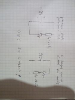
    Listen, I have an urgent question, deviating a bit from the topic, I connected the red LED to the 9V batteries through a 1k ohm resistor and the second one burned out, what is going on? from the right of the ohm there is a current of 9mA and they are on fire, why?
    the connection diagram below, why are they both lit?

    Calculating Apparent, Reactive, and Active Power for Receiver with I=5A, Pn=1000W, Un=230V

    PS I know that the longer leg of the diode is a plus

    Moderated By trymer01:

    Regulations, point 3.1.14. Don't post off-topic messages or in the wrong forum section.
    3.1.17. Publishing entries lowering the general level of discussions, resulting from laziness or containing the demanding nature of statements.
    3.1.15. Publishing entries presenting the problem without providing enough information for other Forum Users to take a substantive position.

  • #29 17054284
    kozi966
    Moderator of Electricians group
    First of all, show us this resistor.
    Second, give us the parameters of the diode you bought.
    Hold_on1 wrote:
    why are they both?

    Because you exceeded their maximum operating current, is it logical?

    By the way, it doesn't matter where you stick the resistor (behind or in front of the diode). The current in this circuit is exactly the same at any point.
  • #30 17054345
    Hold_on1
    Level 6  
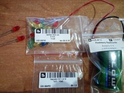
    I bought the whole set for the course "Forbot - basics of electronics part 1", photo of the set used below. Burned LEDs on the left
    Calculating Apparent, Reactive, and Active Power for Receiver with I=5A, Pn=1000W, Un=230V

Topic summary

The discussion revolves around calculating apparent, reactive, and active power for a receiver with a current of 5A, rated power of 1000W, and rated voltage of 230V. The apparent power (S) is calculated as S = U * I, resulting in 1150 VA. The active power is confirmed as 1000W, leading to a reactive power (Q) calculation of Q = S - P = 1150 VA - 1000 W = 150 var. Participants debate the definitions and implications of rated power, the conditions affecting power calculations, and the importance of understanding the power triangle in AC circuits. There are also discussions about the nature of the voltage (AC or DC) and the implications of using incorrect circuit diagrams. The conversation highlights the need for clarity in electrical tasks and the significance of accurate calculations in practical applications.
Summary generated by the language model.
ADVERTISEMENT