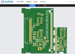
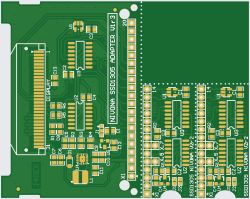
Thank you for the correction.
Quite a few pages already have this topic and in reading I apparently misrepresented.

.
I thought
@satanistik was promoting a solution on programmed memory, while
@amigos and
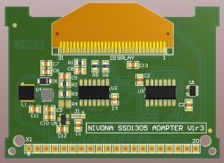
@j4rek supported an option on gates (minimalist version, extended version with inverter placed on TPS to replace original board under display).
Added after 2 [hours] 28 [minutes]: .
>>21624908 .
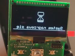
Problem solved.
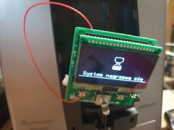
.
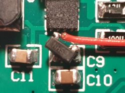
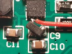
I fitted the MCP1700T-330E/TT stabiliser as provided in the miniature version developed by
@j4rek.
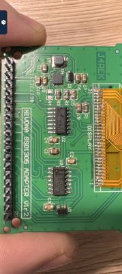
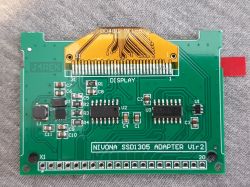
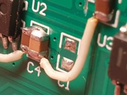
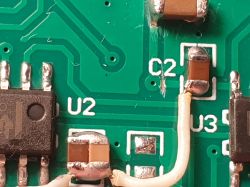
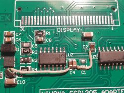
I soldered it 2 legs directly to capacitor C9, on which is the V BAT voltage from pin 3, and its output 3.3V kynar to capacitor C1.
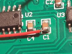
.
.
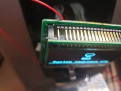
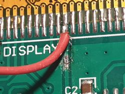
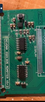
At the same time, in order not to change the VDD voltage for the SSD1305 display applied to pins 11,12 and 13 of the display, I cut the path leading to these pins, and wired a voltage directly from pin 2 of the baseboard to these pins, and soldered pin 2 to disconnect the 2.7V voltage from the baseboard from the 3.3V voltage from the additional stabiliser. As I already had the display glued to the board, I could not cut the path running from pin 2 on the other side of the laminate below the display.
.
.

 .
.
 .
. .
. .
.
 .
.
 .
.
 .
.
 .
.
 .
.
 .
.
 .
.
 .
.
 .
.
