logo elektroda
logo elektroda
X
logo elektroda

Connecting a Universal Central Locking Controller to Astra G '98 Combo: Pin & Color Guide

czkawka2012 18912 9
ADVERTISEMENT
Treść została przetłumaczona polish » english Zobacz oryginalną wersję tematu
  • #1 17252364
    czkawka2012
    Level 9  
    Hello. I want to connect a universal central locking controller. For those who write that there is a search option, I found a lot of topics and I know where the plus and minus is in the cube, as well as not one downloaded the scheme. But I am looking for such a pathological description under which pin or color to sign opening, closing and turn signals in the ankles from the original central lock astra g year 98 combo. And can I also sign for closing the windows? If so, also where? I would rather write a topic than bad solder and write over time.
  • ADVERTISEMENT
  • #2 17252576
    bubu1769
    Level 42  
    Give a diagram or model of this controller what you want to assemble.
  • #3 17252641
    czkawka2012
    Level 9  
    I have a universal scheme that wants to mount, only needs information in which I have to plug into closing, opening, directions and possibly windows to which knives I am sure because the original Astra control panel is without alarm. The original diagram in the attachment
  • ADVERTISEMENT
  • #4 17252734
    bubu1769
    Level 42  
    The Astra switchboard diagram is not interesting to me, I need the diagram from this controller what you want to mount.
  • #6 17253838
    czkawka2012
    Level 9  
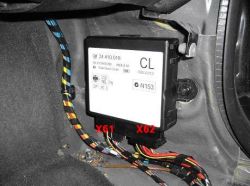
    Maybe someone is writing a list of pins X61 and X62 from the central locking controller? Apparently the same is in Zafir a
  • ADVERTISEMENT
  • #7 17253895
    bubu1769
    Level 42  
    After all, you have it on the diagram that you gave. At night, if I have a moment, I will write you what and how.

    Added after 12 [hours] 8 [minutes]:

    Connecting an additional controller to the original:
    The additional controller should be connected according to the "controlled lock (-)" scheme, and then the brown wire should be connected to the red and white wire in connector X61 of the original controller and the yellow wire to red and white in connector X61.
    Connecting instead of the original driver:
    The additional controller should be connected according to the "direct connection to actuators" scheme and the brown wire should be connected to the black and red wire in the connector X62 of the original controller and the yellow wire to the black and yellow in the connector X62 and the black and blue in the connector X61 (in the case of reverse operation, change places brown and yellow wires).
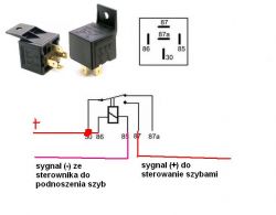
    To close the windows you need to make an inverter on the relay changing the signal (-) to (+), and then connect it to the red-yellow wire in the connector X61 of the original controller.
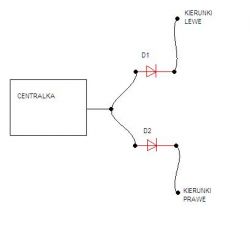
    The flashers should be found in the main bundle black and white and black and green wires with a cross section of 0.75 mm2 and connect to them using rectifier diodes.
    Power can be supplied from brown (-) and red (+) 2.5 mm2 wires in connector X62.
    Connecting a Universal Central Locking Controller to Astra G '98 Combo: Pin & Color Guide Connecting a Universal Central Locking Controller to Astra G '98 Combo: Pin & Color Guide Connecting a Universal Central Locking Controller to Astra G '98 Combo: Pin & Color Guide
  • #8 17261192
    czkawka2012
    Level 9  
    Unfortunately, because connecting the universal controller instead of the original one does not work closing and opening.
  • ADVERTISEMENT
  • #9 17261467
    bubu1769
    Level 42  
    Have you connected the yellow wire to both black and yellow wires in connector X62 and black and blue wires in connector X61?
  • #10 17263490
    czkawka2012
    Level 9  
    So I added a lead so that both were fastened to yellow and I also tried without anything

Topic summary

The discussion revolves around connecting a universal central locking controller to a 1998 Astra G Combo. The user seeks detailed pin and color information for the original central locking system to facilitate the installation. Responses include requests for diagrams and specific wiring instructions. A suggested connection method involves linking the brown wire to the red and white wire in connector X61 and the yellow wire to the black and yellow in connector X62. However, issues arise with the functionality of opening and closing the locks, prompting further troubleshooting and adjustments to the wiring setup. Additionally, there is mention of needing a relay inverter for window control.
Summary generated by the language model.
ADVERTISEMENT