Hello.
In my 1999 V40 (B418S2 engine) it took a long time to replace the variable phase wheel because it was rattling.
Due to lack of time, I delayed the replacement for quite a long time, because apart from the "rattling" the engine worked fine, it did not lose power and there were no other problems. However, a check lit some time ago.
The first time, we managed to delete it and drive as before (about 3000 km). However, the next time the errors returned after the deletion immediately after starting the car. The rattling noise was gone, I conclude that there was already something wrong with the VVT valve (because if the worn out wheel had worked, I would have heard it further). I also had the impression that it slightly weakened (which would indicate that the alternating phases are not working). I made another several thousand with my car.
The computer showed errors P0010 - "A" Camshaft Position Actuator Circuit (Bank 1), P0135 and P0141 (the latter two from the probes).
A few days ago I finally mobilized myself to replace the timing kit with the wheel, I also changed the oil. The engine is completely silent, it works like new (previously warmed up like a diesel), but the check still has not been canceled.
I started looking for the fault myself because the mechanic told me to ignore it. Nobody in the area wanted to do it either.
I was able to find the error P0010 that it concerns this valve. I omit other errors temporarily, because I learned that if I solve the valve issue, they can go out themselves.
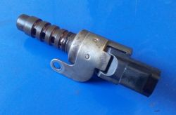
I took out the VVT valve, cleaned it and checked it for 12V - it is operational (it opens and closes).
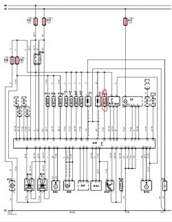
However, by connecting the meter to the wires (red and blue) going to the valve both during the engine operation at low and high revs, I have 0.2-0.5V. The valve does not get the correct voltage from the installation (the check is probably burning because of it?).
After disconnecting the valve and connecting the meter to these wires, I was able to determine that the circuit is not broken, but I do not know what indications should be expected on it.
Please tell me where to find the cause?
Are there any critical installation points where something is rubbing?
I do not want to tear the entire bundle of cables blind.
Could such symptoms indicate a computer failure?
Please help. I changed the timing together with the variable phase wheel, but I can't even use its full potential ...


