logo elektroda
logo elektroda
X
logo elektroda

Correct Network, Capacitor, and Motor Connection for Celma PRCr 10 / 6ES Switch/Regulator

Charles Bronson 10539 6
ADVERTISEMENT
Treść została przetłumaczona polish » english Zobacz oryginalną wersję tematu
  • #1 17308777
    Charles Bronson
    Level 14  
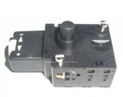
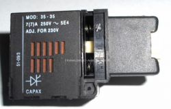
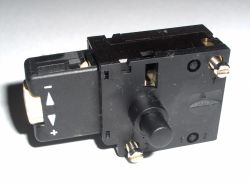
    Hello! How to correctly connect such a switch to the network, capacitor and motor?
    Connection according to photos from another friend's post from the forum: https://www.elektroda.pl/rtvforum/topic2969660.html#14338420 does not satisfy me. There is some regulation, but the stator heats up and the rotor does not reach high speed. The knob, of course, screwed to the max.
    Correct Network, Capacitor, and Motor Connection for Celma PRCr 10 / 6ES Switch/Regulator Correct Network, Capacitor, and Motor Connection for Celma PRCr 10 / 6ES Switch/Regulator Correct Network, Capacitor, and Motor Connection for Celma PRCr 10 / 6ES Switch/Regulator
  • ADVERTISEMENT
  • #2 17308797
    jakubek56
    Level 32  
    Check the connection of the wires again.
  • ADVERTISEMENT
  • #3 17308817
    TomekB123
    Level 20  
    If it heats up does not reach full speed, you most likely have a short circuit in the rotor (read rotor)
  • ADVERTISEMENT
  • #4 17312548
    Akrzy74
    Rest in Peace
    Charles Bronson wrote:
    Hello! How to correctly connect such a switch to the network, capacitor and motor?

    It is not possible for such a switch to work in the network - it is not feasible.
    Connecting from another topic is not satisfactory, why?
    Do you even know how the regulation and start-up department in this drill? I propose to measure the insulation resistance of each of the stator coils and check the rotor on a suitable device.
  • ADVERTISEMENT
  • #5 17312708
    Charles Bronson
    Level 14  
    The presented switch / regulator has two screw terminals for connecting the 230V AC mains voltage and three terminals (numbers 1, 2, 3), which I do not know where to connect because I have not found a schedule anywhere. My guess is that the regulation is in phase and is probably done on a triac. The button is combined with a potentiometer operating in the speed (or power, if you like) control system of the serial motor. I do not want to disassemble this switch to be sure where to connect what. I hope that someone on the forum knows for sure.
  • #7 17312947
    Charles Bronson
    Level 14  
    And that's what I meant. Thank you, my friend Wojtek 9007! Topic is closed.

Topic summary

The discussion revolves around the correct connection of a Celma PRCr 10 / 6ES switch/regulator to a network, capacitor, and motor. The original poster expresses concerns about overheating of the stator and insufficient rotor speed despite maximum knob settings. Responses suggest checking wire connections, potential short circuits in the rotor, and the feasibility of the switch's operation in the network. The poster seeks clarification on the switch's terminal connections, speculating that regulation may involve a triac and a potentiometer for speed control. A related topic about a Capax 35-35 switch is also mentioned, indicating a broader context of similar devices.
Summary generated by the language model.
ADVERTISEMENT