logo elektroda
logo elektroda
X
logo elektroda

Understanding Power Formulas in Three-Phase Motors: P= √3 Uf*If vs P= Uf*If

Xenon02 16467 21
ADVERTISEMENT
Treść została przetłumaczona polish » english Zobacz oryginalną wersję tematu
  • #1 17428230
    Xenon02
    Level 8  
    I have a question about three-phase motors, and more about √3 in power, e.g. active

    Because sometimes I see P= √3 Uf*If

    But when I solve a problem, we suddenly use Pf= Uf*If
    And I don't know why that is...

    I know Up is the phase-to-phase voltage and Uf is the phase-to-phase voltage
    But the task said to calculate the total active power Pc AP= √3 Uf*If it's like 1 load from 3 phases but if you add all 3 it doesn't make sense ....
    Pc= 3Uf*If

    As if someone could explain it to me because I have no idea when P= √3 Uf*If or P= Uf*If


    Thanks in advance for your help as I have not understood this for some time

    Understanding Power Formulas in Three-Phase Motors: P= √3 Uf*If vs P= Uf*If

    Could you explain it as simply as possible? What a boy this is :D
  • ADVERTISEMENT
  • #2 17428884
    Anonymous
    Level 1  
  • #3 17428953
    jack63
    Level 43  
    markus-19 wrote:
    The formulas apply to three-phase alternating current systems.

    You forgot to add that the voltage and current must be a sine wave, we operate on rms values, and the load is symmetrical, i.e. the receivers in the arms of the triangle or star are identical.
    If any of the waveforms (voltage, current) is not a sine wave, these patterns are g worth.
    Nowadays, the voltage still holds the shape (sine wave), but the current is much worse.
    Apparently the task is theoretical, but you need to be aware of the limitations for "patterns", because later flowers come out when measuring the power of, for example, LEDs.

    I removed the unnecessary ones. Please speak on the subject without excursions.[Mod.TM]
  • #4 17428977
    Anonymous
    Level 1  
  • ADVERTISEMENT
  • #5 17429003
    jack63
    Level 43  
    markus-19 wrote:
    certainly the author would like to understand the basics of calculations first,

    The basis of the "calculations" is the scope of their applicability. When we go beyond this range, we count, measure ... the weather.
  • #6 17429272
    Xenon02
    Level 8  
    Thank you markus-19!

    I just checked how it is with active power (probably with other powers) P= U*I*cosφ

    But I saw that the power of 1 three-phase receiver is P = √3*Uf*If*cosφ and it puzzled me a lot. Forgive me for forgetting to mention this, it may be very important

    I also know how it is with symmetric and unsymmetrical three-phase systems.

    And thank you jack63 I didn't know that we operate with effective current but it's worth knowing but when it comes to measurements, I don't do them yet and that's why I want to know the formulas but your advice is also helpful to me! Because soon I'm starting work in connecting but I just don't know yet at what current, whether it's direct or alternating, so I repeat the direct current and alternating current to cope with the practice on adapters (knowledge tests from school) and to understand what the instructor is saying to me .

    Thanks again and I look forward to your reply
  • #7 17430609
    Strumien swiadomosci swia
    Level 43  
    Xenon02 wrote:
    P= U*I*cosφ

    It is on phase 1.

    On 3 phases the power is only √3 higher, not 3 times because the voltages are out of phase.
  • #8 17430638
    Xenon02
    Level 8  
    Then explain to me why P= 3Uf*If*cosφ if you say it should be √3
  • #9 17430663
    jack63
    Level 43  
    Depends on what voltage you substitute into the formula. Phase-to-phase (typically 230VAC) or phase-to-phase (400VAC) voltage
    Note that 400/230=~ 1.73, which is about the square root of 3.
    Remember the assumptions! The formula applies to a symmetrical receiver!
    For a system with asymmetrical reception, e.g. a house powered by 3ph, the current power must be measured or calculated knowing the receivers on individual phases. Because household receivers are usually single-phase and connected in an unbalanced star, there is no multiplier 3, only the sum of the powers of the individual phases.
    He remembers that this is how we can count, measure when the receivers are linear, i.e. their current with sinusoidal excitation is also sinusoidal!
    Such receivers are disappearing at a fast pace. Currents in home installations deviate more and more from the sine wave, so the above method of counting loses its sense.
    You need to be aware of this in order not to make mistakes when measuring.
    Here's an example of such stupidity:
    https://www.elektroda.pl/rtvforum/topic3483634.html
  • #10 17430678
    Xenon02
    Level 8  
    Okay, I think I'm starting to understand about 1-phase receivers in a 3-phase network (let's assume symmetrical) P=√3 Uf*If

    And if not, we add both phases

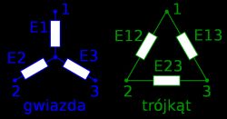
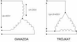
    But I still have a question about the voltage distribution and the current in the triangle and in the star because it is a bit strange in my opinion, e.g. phase-to-phase voltage in the star or current in the star

    Understanding Power Formulas in Three-Phase Motors: P= √3 Uf*If vs P= Uf*If

    Let's say they are dynamos and they create electricity

    So when the star does it, the current goes through E1 and we have Current and Voltage Drop also phase-to-phase, why do we use phase-to-phase?

    And the right question is probably more why we measure both circuits, since if the current has no way to return, e.g. the motor goes such a current and it reaches the resistor, then if there is no 0, e.g. in a triangle, it goes back from phase 1 to phase 2? and in the star that when the current separates, it also returns to the phase? and this voltage drop in the star that phase eg 230 and between 400? then the same current from E1 goes through e.g. E2?
  • #11 17430770
    Strumien swiadomosci swia
    Level 43  
    In the triangle, when the current enters node 2, it spreads evenly to the receivers e12 e23.
    So the current entering node 2 is higher than the current flowing through these 2 receivers together by √3.
  • ADVERTISEMENT
  • #12 17430773
    Xenon02
    Level 8  
    Yes, but where does it return to its "-" because the current goes conventionally from + to -
  • #13 17430787
    Strumien swiadomosci swia
    Level 43  
    Xenon02 wrote:
    Yes, but where does it return to its "-" because the current goes conventionally from + to -


    There is no permanent downside here. Minus constantly changes depending on the moment of time. And it depends on the other 2 phases.

    There is no - or + constant in three-phase current.
    https://www.wykop.pl/link/4162073/trojfazowa-...c-wytlumaczenia-za-pomoca-wody-i-strzykawek/#
  • #14 17430791
    Xenon02
    Level 8  
    Yes, but so that - in the phase where the current flows?
  • #15 17430794
    Strumien swiadomosci swia
    Level 43  
    Current is water, see how it flows every moment in the video.

    And if you can't see it, sponsor yourself 6 syringes and a hose.
  • ADVERTISEMENT
  • #16 17430806
    Xenon02
    Level 8  
    Are you suggesting that the current goes to the receiver and then turns back?
  • #17 17430820
    xury
    Automation specialist
    Xenon02 wrote:
    Are you suggesting that the current goes to the receiver and then turns back?

    And that's 50 times a second :)
  • #18 17430834
    Xenon02
    Level 8  
    Mhmm, so I understood correctly ... the current goes to the receiver, there is no voltage anymore because there was a drop and it comes back because I know that + and - is variable
  • #19 17446568
    mlody1112
    Level 11  
    Power in a DC circuit
    P=U*I
  • #20 18493473
    Xenon02
    Level 8  
    @ Stream of Consciousness
    Strumien swiadomosc... wrote:
    There is no permanent downside here. Minus constantly changes depending on the moment of time. And it depends on the other 2 phases.

    There is no - or + constant in three-phase current.
    https://www.wykop.pl/link/4162073/trojfazowa-...sc-wytlumacona-za-pomoca-wody-i-strzykawek/#


    There is no permanent minus, but there must be a closed circuit, so where is this lower potential where the current flows for a short while?

    In the video, I noticed that if the phase, say, F1 (red) is at its peak, the temporary minus is the phase F2 (yellow syringe) and F3 (blue syringe). I do not know how to put it in words so as not to offend anyone from the professionals here, but I will say that F2 consumes less power and F3 a little more and F1 only supplies current. Phase-to-phase and phase-to-phase voltages can be calculated.

    Am I a bit right here?
  • #21 18496078
    Aleksander_01
    Level 43  
    I'll throw in my two cents.
    You're right.
    Regarding the main question why P=√3UpIp.
    Think of the receiver as a "black" box (symmetric, you don't know how it is paired, whether Δ or γ ;) . The general formula is 3x UfIf . If the receiver is Δ, so Uf = Up and the current Ip is greater than If by √3. If the load is γ then Uf is √3 smaller than Up and the line current is equal to the phase current.
    Therefore, the general formula for active power (for R) P = √3UpIp, and therefore general because it is easiest to implement, just measure Up and Ip of one phase and you have the total load power.
    Practice a bit on resistors (symmetric receiver) and you will see that no matter how you calculate the total power will always be the same.
  • #22 18517468
    retrofood
    VIP Meritorious for electroda.pl
    Xenon02 wrote:
    I have a question about three-phase motors, and more about √3 in power, e.g. active

    Because sometimes I see P= √3 Uf*If

    But when I solve a problem, we suddenly use Pf= Uf*If
    And I don't know why that is...

    First of all, you need to pay close attention to the indices next to the symbols of individual quantities. Because P is not the same as P f. A for example AT p is not equal AT f in a star system. Phase and conductor sizes are different.

Topic summary

The discussion revolves around the confusion regarding power formulas in three-phase motors, specifically the differences between P = √3 Uf*If and P = Uf*If. Participants clarify that the formula P = √3 Uf*If applies to three-phase systems, where Uf is the phase-to-phase voltage and If is the phase current, while P = Uf*If is typically used for single-phase calculations. The importance of understanding the context of symmetrical versus asymmetrical loads is emphasized, as well as the significance of using effective (rms) values for voltage and current. The conversation also touches on the behavior of current in different configurations (star vs. delta) and the implications for power calculations in practical applications.
Summary generated by the language model.
ADVERTISEMENT