logo elektroda
logo elektroda
X
logo elektroda

Does Resistor Orientation Matter in Soldering Due to Color Bands?

serwkomp 18903 32
ADVERTISEMENT
Treść została przetłumaczona polish » english Zobacz oryginalną wersję tematu
  • #1 17650056
    serwkomp
    Level 6  
    Hello.

    I read and ask questions.
    I understand that it makes no difference which side the resistor is soldered in, e.g. https://www.google.com/search?q=rezystor&clie...CpwQ_AUIDigB&biw=1280&bih=888#imgrc=81klBoOys wDn7M:

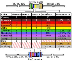
    There are four colors, I understand that it doesn`t matter which side I solder - brown or gold?
    I understand that the colors mean the power of the resistor and nothing else?

    Of course, I mean a resistor with two legs.
  • ADVERTISEMENT
  • #2 17650061
    marekhab
    Level 33  
    You can solder the resistor in any direction.
  • ADVERTISEMENT
  • #4 17650063
    kacpo1
    Level 33  
    serwkomp wrote:
    I understand that the colors mean the power of the resistor and nothing else?

    NO. Resistor resistances.
    Does Resistor Orientation Matter in Soldering Due to Color Bands?
    Which side you solder doesn`t matter.
  • #5 17650073
    serwkomp
    Level 6  
    Thank you for your help. I soldered a resistor to the LED lamp, I soldered the resistor once, starting from the brown color, the lamp lights up and then, inversely, from the gold color to the LED leg, the lamp also lights up. So I thought I`d ask if soldering the resistor would be good anyway and wouldn`t burn the LED.
  • #6 17650269
    zybex
    Helpful for users
    The side is indifferent. Just like you take a regular light bulb and connect it to a battery. The colors indicate the resistance value but do not indicate the power. The size of the resistor determines its power. Here it is not as obvious as in the case of resistance. In any case, if you take more power and you don`t mind how much space it takes up, it`s always better than taking too little power. Then the resistor will overheat and eventually burn out.
  • #7 17650351
    yogi009
    Level 43  
    However, my friend, the author, should read something . I haven`t seen a question at this level for a long time.
  • #8 17651220
    _jta_
    Electronics specialist
    I would suggest soldering the resistor in such a way that the direction of reading its value is the same as its markings on the board. It will be easier to read when needed.
  • #9 17651234
    sosarek

    Level 43  
    _jta_ wrote:
    I would suggest soldering the resistor in such a way that the direction of reading its value is the same as its markings on the board.

    Dude, don`t joke - even equipment manufacturers don`t follow this rule.
    Helpful post? Buy me a coffee.
  • #10 17651267
    yogi009
    Level 43  
    sosarek wrote:
    even equipment manufacturers do not apply such a rule


    And this depends on the manufacturer.
  • #11 17651288
    _jta_
    Electronics specialist
    If the manufacturer does not intend to repair the equipment in the event of damage to the electronics, then the orientation of resistors is unnecessary. ;)
  • #12 17651298
    yogi009
    Level 43  
    Certainly decent designs (especially visible in THT elements) had resistors oriented this way.
  • #13 17651455
    zybex
    Helpful for users
    _jta_ wrote:
    I would suggest soldering the resistor in such a way that the direction of reading its value is the same as its markings on the board. It will be easier to read when needed.

    This is such "pedantism". When I read the resistor values on the board of a given device, I don`t even pay attention to how it is soldered. I just know that it is of such value and that`s it.
  • #14 17651500
    szogun
    Level 23  
    A simple question. The simple answer has already been given. Maybe Learned Heads would stop cluttering up the topic and the Forum!?
    Unless they increase their rank, that`s a different story...
  • ADVERTISEMENT
  • #15 17651600
    janek1815
    Level 38  
    _jta_ wrote:
    I would suggest soldering the resistor in such a way that the direction of reading its value is the same as its markings on the board. It will be easier to read when needed.


    Well, I wouldn`t have thought of that. From now on, I will look at all devices to see how the resistors are mounted. Like all over the world, the price for repair is much higher because the manufacturer did not provide for the repair. ;)
  • #16 17651609
    zybex
    Helpful for users
    szogun wrote:
    A simple question. The simple answer has already been given. Maybe Learned Heads would stop cluttering up the topic and the Forum!?
    Unless they increase their rank, that`s a different story...

    Well, your post is an example of increasing your rank. It adds absolutely nothing to the topic. Just like mine now. Anyway, mine can now be deleted to the trash. The important thing is that the author now knows more about the question asked.
  • #17 17652186
    398216 Usunięty
    Level 43  
    If the manufacturer puts it in as it pleases, it`s no wonder. Serial production, so no one cares about aesthetics and comfort, but about quantity.
    Personally, in my designs I use the rule that resistors can be read from left to right or top to bottom (assuming one side of the PCB as the base/bottom).
    This is of course not mandatory - if you do not solder the resistor, it will still work the same, but first of all, such a "tidy" board looks more aesthetically pleasing, and it is also easier to avoid reading errors if, for example, the resistor burns out or changes color.
    I remember the times when only the right resistors had numbers and letters printed on them, and it was incredibly annoying when the manufacturer (the lady on the tape) soldered such an inscription to the board. Perhaps this is where my love for systematizing the arrangement of elements comes from - why go against it if you can make your life easier without much effort?
  • #18 17652307
    yogi009
    Level 43  
    I have the same habit, also in SMD. I look through the magnifying glass and everything is clear to me, without any combination.
  • ADVERTISEMENT
  • #19 17652364
    ArturAVS
    Moderator
    yogi009 wrote:
    I have the same habit, also in SMD

    Me too. Whether through-hole or SMD.
  • #20 17652438
    zybex
    Helpful for users
    398216 Usunięty wrote:

    Personally, in my designs I use the rule that resistors can be read from left to right or top to bottom

    I guess everyone who cares about aesthetics has done this. I always made sure that the resistor was soldered evenly. When soldering the first leg, I took pliers (or tweezers) and positioned the resistor so that it was parallel to the neighboring elements.
    Often, in factory products, assembly was much less aesthetic.
    398216 Usunięty wrote:

    I remember the times when only the right resistors had numbers and letters printed on them, and it was incredibly annoying when the manufacturer (the lady on the tape) soldered such an inscription to the board.

    It was really annoying, because you had to unsolder at least one of its ends to see its value. After entering the barcode, the problem resolved itself. By the way, do you remember resistors that had values given in the form of colored dots? However, these had radial leads, and the mentioned value in such resistors was always at the top.
  • #21 17652472
    ArturAVS
    Moderator
    zybex wrote:
    the mentioned value in such resistors was always at the top.

    Theoretically. It depended on the installer.
  • #22 17652474
    zybex
    Helpful for users
    arturavs wrote:
    zybex wrote:
    the mentioned value in such resistors was always at the top.

    Theoretically. It depended on the installer.

    I meant resistors with radial leads, not axial ones.
  • #23 17652518
    ArturAVS
    Moderator
    zybex wrote:
    I meant resistors with radial leads, not axial ones.


    They must have been quite powerful?

    Once, I left a few boards for my "ex" to solder. In fact, she soldered. But each resistor basically goes in a different direction.
    I asked why so? and not equally? That is, the tolerance bar is on the right side.

    "I thought the tile would look nicer this way"

    What was I supposed to say? It worked.
  • #24 17652661
    zybex
    Helpful for users
    arturavs wrote:

    They must have been quite powerful?

    Not at all. They were used, among others, in small portable radios. I used to have quite a few of these types of resistors. Today I don`t know if I could find even one at home.
  • #25 17653020
    398216 Usunięty
    Level 43  
    zybex wrote:
    Do you remember resistors that had values given in the form of colored dots?
    I even have a dozen or so 0.5 Ohm 0.5 W of these... :) (axial leads).
  • #26 17653058
    zybex
    Helpful for users
    If I find the ones I wrote about in the junk somewhere, I will post a photo. As you can see, not everyone even knows about the existence of such resistors. So-called capacitors are probably equally rare. "potato" boxes or others in glass casings sealed on the sides with tar or some kind of adhesive.
  • #27 17653101
    398216 Usunięty
    Level 43  
    As for resistors (old ones, with dots or letter-digit descriptions), there is no problem - they can be used even today, nothing bad will happen to them (unless someone helps... ;) ). However, you won`t see "potatoes" or capacitors covered with tar today, and their possible use (if someone still has something like this in their collection) doesn`t make any sense; At the time of production, they did not have excellent parameters, and after many years - even when lying in a box - unfortunately, they lose their parameters. In devices operating several hours a day (e.g. in RO), where they were installed, after a few years they began to "swell" (potatoes), resembling the appearance of a potato pulled out of a fire and split in half - hence the name - and to this day, none of them have been used. survived due to the need for replacement.
  • #28 17653139
    zybex
    Helpful for users
    When writing about old types of capacitors or even resistors, I did not mean to use them. Many young people have simply never seen such elements and it is worth at least mentioning them sometimes. For example, there were popular germanium transistors painted with black paint that could be easily scratched off. In this way we had a phototransistor useful in many projects.
  • #29 17653190
    398216 Usunięty
    Level 43  
    zybex wrote:
    I didn`t mean to exploit them
    And me too. I was simply trying to explain the history of such terminology :) At the same time explaining that not everything that is "old" is necessarily bad. While reading topics on the forum, I saw at least a few in which the authors started the repair (regardless of what the fault was) by replacing e.g. capacitors because "if they are old, they are definitely worn out", while many 30-year-old and even older capacitors are still fully efficient. Similarly, resistors - "...the resistor got hot, so I replaced it"... While in fact the only correct method of verifying whether a given element qualifies for replacement is measurement - with an appropriate tester (e.g. there were electrodes in the store), or even an ohmmeter, a meter with a diode or transistor test function.
  • #30 17653215
    olaf x
    Level 34  
    zybex wrote:
    arturavs wrote:
    zybex wrote:
    the mentioned value in such resistors was always at the top.

    Theoretically. It depended on the installer.

    I meant resistors with radial leads, not axial ones.


    I remember these, I haven`t played with electronics yet, but I saw them in some equipment, they didn`t have wires at the ends, but narrow plates pointing in one direction, for soldering, so you would have to be very stubborn to solder them in the opposite direction. And the dots were just at the front.

Topic summary

The discussion centers around the orientation of resistors during soldering, specifically whether it matters which side is connected to the circuit. Participants agree that the orientation does not affect functionality, as resistors are non-polarized components. The color bands on resistors indicate resistance values, not power ratings, which are determined by the resistor's size. Some contributors suggest that for aesthetic and practical reasons, resistors should be oriented consistently for easier reading of their values on the circuit board. However, it is noted that manufacturers often do not adhere to this practice, and the orientation is largely a matter of personal preference. The conversation also touches on historical resistor types and the importance of proper measurement for component replacement.
Summary generated by the language model.
ADVERTISEMENT