logo elektroda
logo elektroda
X
logo elektroda

Arduino Mega 2560 and CNC Shield v.3 - Is it compatible with GRBL?

raro 9072 16
ADVERTISEMENT
Treść została przetłumaczona polish » english Zobacz oryginalną wersję tematu
  • #1 18562462
    raro
    Level 12  
    I have a question for my colleagues who are knowledgeable on the subject.
    Is it possible to "force" Shield CNC v.3 to work with Arduino Mega 2560 with GRBL loaded?
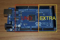
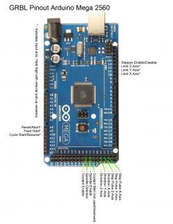
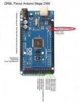
    It is true that sellers claim that MEGA 2560 is compatible with Shield CNC just like UNO, but this is probably not true. Arduno UNO with GRBL works with Shield CNC without any problems, but MEGA does not! From what I managed to find out, the appropriate pinouts in both boards are not in the same places (pins).
    Do you have a problem with Arduino? Ask question. Visit our forum Arduino.
  • ADVERTISEMENT
  • #3 18563264
    raro
    Level 12  
    Ok, but after inserting the CNC Shield with stepstics and connecting the motors, they are blocked. I think (probably) the STEP and DIR pinouts are on different pins than in UNO.
  • #4 18563811
    Anonymous
    Level 1  
  • ADVERTISEMENT
  • #5 18563833
    Slawek K.
    Level 35  
    Just upload the GRBL intended for the UNO to the Mega and it will work with the UNO shield, and if you want to use the GRBL dedicated to the Mega, you have to use the shield for the Mega, but that`s probably rather obvious.

    Regards
  • #6 18564132
    raro
    Level 12  
    Thank you for your interest in the topic and the information sent.
    Sławek K . - unfortunately it doesn`t work like that. It is possible to upload grbl intended for UNO to MEGA, but programs for controlling the device, e.g. UGS (Universal Gcode Platform), do not "see" it.
    emarcus - you confirmed my fears that it cannot be done (connect MEGA with the Uno shield). I thought maybe I could do something programmatically in the config (change the mapping).
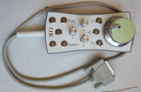
    I explain why I "circle" around Mega if my device works on Uno. Well, I made myself a small CNC milling machine. I use Estlcam for control. I found a description of how to make a joystick ( Link ) but it needs to be connected to Mega.
  • #7 18564173
    Slawek K.
    Level 35  
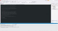
    Well, it is possible to upload grbl on Uno to mega, screenshot below:

    Arduino Mega 2560 and CNC Shield v.3 - Is it compatible with GRBL?

    And in this case, the shield dedicated to Uno works.

    Nevertheless, you cannot use additional pins from Mega because Uno has a maximum of 20.
    So you won`t do what you want, i.e. add a joystick, because the software dedicated to Uno will not support it.

    Regards
  • #8 18564288
    raro
    Level 12  
    Sławek K. - Yes, it is possible to upload grbl intended for Uno to Mega, but as I wrote earlier, programs for controlling CNC devices do not "see" it - at least that`s the case for me (unless I`m doing something wrong).
    Everything works on Uno! Of course, you can`t use the joystick in this configuration.
    Have you tested "your theory" in practice?

    Added after 9 [hours] 18 [minutes]:

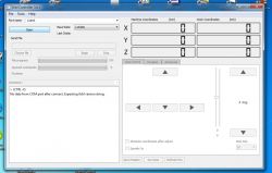
    After uploading the UNO version to MEGA grbl 1.1h in the GRBL Controller, I receive the message as in the attached scan:
    Arduino Mega 2560 and CNC Shield v.3 - Is it compatible with GRBL?
  • ADVERTISEMENT
  • #9 18580161
    raro
    Level 12  
    I`m still waiting for some helpful news.
    Unfortunately, I don`t know how to create codes for Arduino, but I have a question for those familiar with the subject. Isn`t it possible to reprogram grbl to " redirecting appropriate signals to appropriate pins " (probably in the cpu_map file) so that it corresponds to the CNC shield (Shield CNC V3).
    I hope I described the matter in an understandable way.
  • ADVERTISEMENT
  • #10 18582130
    Anonymous
    Level 1  
  • #11 18582464
    raro
    Level 12  
    "emarcus" - thanks for the information.
    I have already read this thread. The same problem as mine is described there, with a minor exception regarding the stepstic used (I use A4988). As I wrote earlier, I don`t know much about programming and I don`t fully understand the posts there. I think the most important post there is #12. If I understood correctly, the solution would be to make a new/own CNC shield board with an appropriately changed arrangement of the STEP and DIR pins to match the pins in the Arduino Mega 2560.

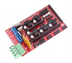
    As for the use of another driver, I have RAMP 1.4, but using it for my project is a bit difficult due to the fact that it is basically intended for 3D printers and if used for a CNC milling machine, it would require a bit of fiddling. However, the most important thing is that it will not work with the joystick you made. I received this information from the author of the Estkcam program (it`s hard to get information from him - he doesn`t want to answer e-mails, and when he does answer, it will be in a few words). When I started building the joyski, I was convinced that there would be no problems. I thought that I would only replace UNO with MEGA and it would be OK. I bought Arduino Mega 2560 in the Modeling Wholesale Store ABC-RC-Arduino-RC-Models-Drony and in the description of the CNC V3 shield it is written that it is compatible with Uno and Mega!!! This got me into trouble. The milling machine on the Uno works without any problems, but I will not use the joystick I made.
  • #12 18588518
    raro
    Level 12  
    If anyone is interested in the topic, I would like to inform you that I have made progress and "forced" the CNC V.3 shield to "work" with the Arduino Mega 2560. For now, I have checked the operation of the X, Y, Z axis motors. THEY WORK!
    How did I do it? Using the grbl file information (for Mega 2560) cpu_map.h :
    // Define step pulse output pins. NOTE: All step bit pins must be on the same port.
      [code]#define STEP_DDR      DDRA
      #define STEP_PORT     PORTA
      #define STEP_PIN      PINA
      #define X_STEP_BIT    2 // MEGA2560 Digital Pin 24
      #define Y_STEP_BIT    3 // MEGA2560 Digital Pin 25
      #define Z_STEP_BIT    4 // MEGA2560 Digital Pin 26
      #define STEP_MASK ((1<<X_STEP_BIT)|(1<<Y_STEP_BIT)|(1<<Z_STEP_BIT)) // All step bits
    
      // Define step direction output pins. NOTE: All direction pins must be on the same port.
      #define DIRECTION_DDR     DDRC
      #define DIRECTION_PORT    PORTC
      #define DIRECTION_PIN     PINC
      #define X_DIRECTION_BIT   7 // MEGA2560 Digital Pin 30
      #define Y_DIRECTION_BIT   6 // MEGA2560 Digital Pin 31
      #define Z_DIRECTION_BIT   5 // MEGA2560 Digital Pin 32
      #define DIRECTION_MASK ((1<<X_DIRECTION_BIT)|(1<<Y_DIRECTION_BIT)|(1<<Z_DIRECTION_BIT)) // All direction bits
    
      // Define stepper driver enable/disable output pin.
      #define STEPPERS_DISABLE_DDR   DDRB
      #define STEPPERS_DISABLE_PORT  PORTB
      #define STEPPERS_DISABLE_BIT   7 // MEGA2560 Digital Pin 13
      #define STEPPERS_DISABLE_MASK (1<<STEPPERS_DISABLE_BIT)[/code]

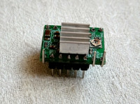
    I changed the connections of the STEP and DIR pins of individual A4988 stepsticks and the ENABLE pin accordingly (as shown above).
    I "prepared" stepstcki A4988 as in Photo_1. In Photo-2 I present test connections for two axes (X and Z).
    Now I need to check the remaining connections: STOP, PROBE, spindle speed control. I think it can be done. The final check will be to test my joystick.
  • #13 18742754
    raro
    Level 12  
    After a long break, I`m back to the topic.
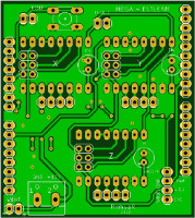
    I designed my own "shield" and ordered the board to be made from the Chinese. After a month of waiting, I received the ordered tiles. I soldered the elements and the tests were positive. I only have one doubt. Well, it turned out that the Mega 2560 with the Estlcam software loaded does not provide the "Stepper Enable/Disable" signal, which in the case of the GRBL software loaded is on pin 13. In this situation, the ENABLE pin of the A4988 controller will "hang in the air" (it will be on all the time). forced low level) and the engine will be powered all the time, which will result in greater heating of the controller and the engine. There will be the so-called holding moment.
    And here I have a question for experienced colleagues. Is this solution correct?
  • #14 18742972
    Anonymous
    Level 1  
  • #15 18743072
    raro
    Level 12  
    Thanks for the information.
    As I understood, working with the lack of external connection to the EN pin is correct. Or so?
    I checked the heatsink temperature on the A4988 chip. During "standstill" the temperature was approximately 55 - 60 degrees C, during operation it reached 72 degrees C. Isn`t this too high?
  • #16 18743630
    Anonymous
    Level 1  
  • #17 18744210
    raro
    Level 12  
    emarcus - Thank you for the very professional information. I just don`t really understand how I can use microstepping to lower the motor current using table 2 in Datasheets A4988.
    I will also check the operation of the entire system (Mega 2560 + Shield) in the designed housing, which I equipped with a 4010 12V fan.

Topic summary

The discussion centers on the compatibility of the Arduino Mega 2560 with the CNC Shield v.3 when using GRBL firmware. Users express concerns that while the Arduino UNO works seamlessly with the CNC Shield, the Mega 2560 does not due to differing pin configurations. Some participants suggest that it is possible to upload GRBL intended for the UNO to the Mega, but controlling software like UGS fails to recognize it. A workaround involves modifying the cpu_map.h file in GRBL to redirect signals to the appropriate pins for the Mega, which some users have successfully implemented. However, there are warnings about the limitations of using the UNO firmware on the Mega, particularly regarding additional functionalities like joystick integration. The conversation also touches on the thermal management of stepper drivers like the A4988 and the importance of proper pin connections to avoid overheating issues.
Summary generated by the language model.
ADVERTISEMENT