logo elektroda
logo elektroda
X
logo elektroda

How to check with a meter which cable is 0 and which is phase

JohhnyCage11 83748 39
ADVERTISEMENT
Treść została przetłumaczona polish » english Zobacz oryginalną wersję tematu
  • #31 18845702
    takijasiu
    Level 25  
    JohhnyCage11 wrote:

    Sure please

    PS If something is wrongly done (done about 5 years ago), do I have the right to call him and tell him? All in all, it was paid to the construction company, and she hired an electrician.

    How to check with a meter which cable is 0 and which is phase


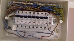
    In this photo you can see various interesting bugs:

    - the switchgear has no main switch - the power supply is supplied to the comb that is connected to the lower connectors of the apparatus

    - the presence of the Żo conductors (protective conductor, this is the yellow-green one) indicates that the installation is three-core - but the question of what is the entire protective rail connected to - it cannot be seen in the photo - correctly, depending on the type of power supply network (TN, TT) this rail should be properly handled

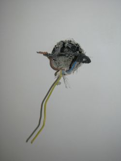
    - eeee - regarding the above point - because I did not get a little sleep today - there are wires in the switchgear, but there are no cables in this example socket - this is a question what the masters have done with them - it is not sometimes that the fuse box was in another place and they moved it by adding pieces of 3-wire cables? if you can see something in the switchgear, it should of course also be in the socket - and it is not there

    - lack of a residual current device required by law (Regulation)

    - too large denominations - B20 - there cannot be a socket on the perimeter behind such a device, because the socket has a strength of 16A, and besides, there cannot be a 2.5mm? cable, and probably it is - also the question is why as many as 3 such devices

    - similarly, if you have any lighting with switches, it is also too large a value, because most household switches have a strength of 10A

    - plus the fact that I counted 8 blue wires on the neutral bus, and there are also 8 overcurrent switches, there is also a separate switch for each circuit

    - the supply of cables in the switchgear is too large left

    - I wonder if the bell is secured
  • ADVERTISEMENT
  • #32 18845703
    Anonymous
    Level 1  
  • ADVERTISEMENT
  • #33 18845789
    kaz69
    Level 36  
    It should not be built and released for use.
  • #34 18845943
    kkkamil
    Level 13  
    kkkamil wrote:
    Heh, the peasant asked a specific question and, as usual, electricians turned out to be philosophers.

    Answer:

    You set the range to alternating voltage (NOT CURRENT!) And take one wire in the paw (yes, the metal one in your hand) and the other pole to the contact. On phase you will have an indication of around 50V, on zero you should have 0V. Of course, this is not professional and "do not do it at home", but if there is no way out ...

    The method is a bit dangerous because if you connect the wires for measuring the current by mistake, you will find out for yourself that you have found the phase. So if you are not familiar with the meter, maybe it's better to call an electrician or buy a neon lamp (a few zlotys is enough).

    greetings. Kamil

    ["kozi966"] You get warnings for such advice on this forum, and that is how it ends in this case.
    This is a highly DANGEROUS tip.
    3.1.11. Publishing posts that do not contain substantive content, with harmful advice, advice that is not an attempt to fix the problem, and posting identical posts in succession or repeating information from the discussion. [/ Mod]


    I understand, thank you for the shot in the back of the head (I got a warning or something), I will not speak again here. Measurement with the multimeter that I gave is healthier for the meter and safer than with neon - much less current flows through a human. But ok. I understand, I will not tell you how to safely measure in the absence of dedicated tools. I don't consider myself guilty.

    Greetings. Kamil.

    Moderated By Łukasz-O:

    I suggest avoiding the electric cannons with a wide arc.

  • #35 18845952
    Łukasz.K
    Level 28  
    The meter may be damaged at any time, shocking the measuring person. Therefore, this method is dangerous.
  • ADVERTISEMENT
  • #36 18846270
    gkwiatkowski
    CCTV and Stationary Alarms specialist
    kkkamil wrote:
    Łukasz.K wrote:
    The meter may be damaged at any time, shocking the measuring person. Therefore, this method is dangerous.


    I have been using multimeters for 40 years, I have never met at home or with anyone that my friends say that the multimeter would be damaged in this way. But what do I know ...

    Anyway, I am finishing the discussions in this thread because the moderator will finish me off with penalties, if someone has any more comments for me, I invite you to the priva.

    Greetings. Kamil


    The author of the topic is unfamiliar with electricity and may make a mistake in setting the meter. The layman does not distinguish between what is current, voltage, U, V, I, A. He will set it to measure the intensity of the current and he will hurt himself.
    The method of measuring dangerous voltage with a multimeter and your own body can only be proposed to someone very experienced, but only on the basis of MacGywer's final method in the absence of access to civilization.
    Let the author of the topic go to an electrical store and buy a neon lamp for PLN 5.
  • #37 18846630
    RNIC
    Level 15  
    For 5 zlotys, it is already "great". The prices of neon samplers range from ~ 3 to ~ 10 PLN.
    Go to the store, buddy, buy a sampler and then you can safely check which phase it is. Unfortunately, when you see a switchgear with 3-core cables and at the same time in only 2 sockets, the knife in your pocket opens by itself. Well, unless the builders just added new circuits to the old existing installation.
    And this, in the absence of knowledge of the subject, for the person asking the question will probably be the safest solution to the question asked.
    Although a visit by a kumaty electrician is also advisable.
  • ADVERTISEMENT
  • #38 18847053
    JohhnyCage11
    Level 5  
    There was an electrician I asked for, but not the same electrician who had done anything here in the past. He also stated the same:

    What he said:
    -the builders used the existing cables already in the wall and added their own 3-wire cables here and there.
    - despite the fact that they added new 3-wire here and there, and so in not all of these places the protective cable was connected (electrician's surprise and mine too)
    - therefore, the sockets in which there was no protective cable (or it was, but not connected at all) applied a patent (if I understood it correctly) - the ground cable first to the pin and from the pin to the ground input in the socket. He said it was always more than nothing.
    -said that in the box it would be necessary to exchange these devices for other ones, because the ones I have are "exaggerated" with the cables I have.
    - the possibility of installing a RDC, although he emphasized that with these cables it makes sense on average ..

    He had a nice large device (computer) with him, as he claims for several thousand, and there I saw he made various measurements on the display, he had a lot of equipment in general.

    When I asked him how to distinguish between a ground cable and a protective cable (he was looking at this large device after it was connected). He said that "you can use a meter", I connect one probe to the phase and the other to the other cable - if the indication is 0 it is "rather protective", although he ordered to buy a multimeter with RFM and then it shows, for example, ~ 50 ..
  • Helpful post
    #39 18847063
    elpapiotr
    Electrician specialist
    JohhnyCage11 wrote:
    What he said:
    -the builders used the existing cables already in the wall and added their own 3-wire cables here and there.
    - despite the fact that they added new 3-wire here and there, and so in not all of these places the protective cable was connected (electrician's surprise and mine too)
    The builders took advantage and took advantage of their and their client's ignorance and dragged him to pointless costs. Normal operation for tricksters, but as the saying goes:
    The old truth says - " a bricklayer and a forester are not a craftsman. And the painter is fern "
    The obvious fault of the client / principal, who should know that the builders do not know each other and will not know about electricity.
    I meet such flowers often, even here:

    How to check with a meter which cable is 0 and which is phase
  • #40 18848220
    xray81
    Level 22  
    Such a meter is a multimeter and you need to know how to use it, although the Unit releases meters with help where the display shows where to connect the "probes" at the selected setting, but you still need to know what setting the multimeter to choose. It's best if you use a bipolar meter in German called Duspol, e.g. something like UNI-T UT18C where one of the probes will show you where the phase is.

Topic summary

The discussion revolves around using a UNIT-T UT 33C multimeter to identify phase and neutral wires in an apartment's electrical installation. Users suggest measuring voltage between the wires and a grounded point, such as a water pipe, with the expectation that the phase wire will show approximately 230V while the neutral wire will show 0V. Concerns are raised about the safety and accuracy of this method, with recommendations to use a neon indicator for safer measurements. The conversation also highlights issues with the existing electrical installation, including the absence of RCDs and proper grounding, and the need for professional electrical work to ensure safety and compliance with regulations.
Summary generated by the language model.
ADVERTISEMENT