logo elektroda
logo elektroda
X
logo elektroda

Overcoming 253V Voltage Limit in German Standards: VDR AR-N4105, BDEW, VDE 0126

hermi1 23985 22
ADVERTISEMENT
Treść została przetłumaczona polish » english Zobacz oryginalną wersję tematu
  • #1 19299419
    hermi1
    Level 5  
    Gentlemen

    Which standard for Germany? The voltage sometimes slightly exceeds 253V and I would like to eliminate this problem by increasing the voltage limit. I have such:

    Germany VDR AR-N4105
    Germany BDEW
    Germany VDE 0126

    Thank you in advance
    Moderated By krzysiek7:

    I merged the topics.
    3.1.12. Do not post multiple identical topics in the forum, users will not know where to reply.

  • ADVERTISEMENT
  • #2 19299492
    theo33
    Level 27  
    hermi1 wrote:
    Gentlemen

    Which standard for Germany? The voltage sometimes slightly exceeds 253V and I would like to eliminate this problem by increasing the voltage limit. I have such:

    Germany VDR AR-N4105
    Germany BDEW
    Germany VDE 0126

    Thank you in advance


    First, check what is the reason for the voltage increase, whether your section from the measuring system to the meter or the power grid is too soft
    As for the norm, you have country 12 in the sofa and it should be selected
  • #3 19299532
    hermi1
    Level 5  
    theo33 wrote:
    hermi1 wrote:
    Gentlemen

    Which standard for Germany? The voltage sometimes slightly exceeds 253V and I would like to eliminate this problem by increasing the voltage limit. I have such:

    Germany VDR AR-N4105
    Germany BDEW
    Germany VDE 0126

    Thank you in advance


    First, check what is the reason for the voltage increase, whether your section from the measuring system to the meter or the power grid is too soft
    As for the norm, you have country 12 in the sofa and it should be selected


    The problem is the network, today I talked to my neighbor and he has the same problem. We will report the matter to PGE, but I wanted to somehow temporarily solve the problem. Changing country won't help?
  • #4 19299551
    Anonymous
    Level 1  
  • #5 19299564
    krzysiek7
    Moderator of Electricians group
    hermi1 wrote:
    We will report the matter to PGE, but I wanted to somehow temporarily solve the problem. Changing country won't help?

    Have you thought about what can happen to all kinds of equipment, especially those expensive, connected to the network, both at your place and at your neighbors?
  • ADVERTISEMENT
  • #6 19299943
    Anonymous
    Level 1  
  • ADVERTISEMENT
  • #7 19300096
    hermi1
    Level 5  
    Gentlemen

    Calm down, don't be nervous... Maybe I wasn't fully aware of the problem and potential consequences - I won't change anything in that case and I'll try to settle the matter through PGE and ask for lowering the voltage on the transformer. The problem is not permanent and so far the inverter turns off once every few days for several minutes.
    But out of pure curiosity, I would still like to know what is the difference between the standards for Germany that I asked about?
  • #8 19300412
    rafbid
    Level 33  
    hermi1 wrote:
    The problem is the network, today I talked to my neighbor and he has the same problem. We will report the matter to PGE, but I wanted to somehow temporarily solve the problem.
    Try to change your habits to increase self-consumption during peak production hours.
  • #9 19367767
    darkened616
    Level 5  
    hermi1 wrote:
    I will try to settle the matter through PGE and ask for lowering the voltage on the transformer


    And how did PGE respond?

    I have a similar problem, a 1-phase inverter, it turns off on sunny days and kiss it. I rummaged in the inverter settings and it turned out that the Dutch standards were set, so I switched to PL, which seems to have helped a little but the inverter still turns off. I called PGE and they said that they have a lot of such reports, but they can't do anything because they would have to install transformers with automatic voltage regulation, and it costs money. What's more, they also said that they have an increasing problem with medium-voltage lines because the mass-installed PVs increase the voltage there and they have to modernize them. Coming back.... the prosumer contract says that the prosumer should consume the energy he produces on an ongoing basis, and any surpluses (note quotes here) the network MAY but DOES NOT HAVE to accept. I, on the other hand, in the regulations ("Regulations for the performance of comprehensive contracts for the sale of electricity, the provision of distribution services and the provision of collection and settlement services for electricity introduced into the DSO network from micro-installations"), I see a provision that "The seller undertakes to the prosumer to: 1. Collect electricity produced in the Microinstallation provided by the prosumer." So I don't know how it is, whether they MUST or CAN .... However, the subsidy program in the municipality for PV is in full swing, the installed PVs do not work because of the high voltage in the grid, ba .... the municipality itself set up a farm that does not work .... and they continue to collect applications for funding .... this is Poland ....
    Now I'm trying to figure out how to load the grid so that PV continues to work on sunny days. I'm thinking about some kind of smart socket and water heating.
  • #10 19367812
    toolpusher
    Level 23  
    I don't have this problem with the voltage, but I have a Gosund socket and I heat the water in the boiler for 2-3 hours during the largest production or until the temperature on the regulator is reached. The Gosund socket has app control and electricity and energy consumption measurement. I just don't know if it will help if there is such tension in the whole commune.
  • #11 19368363
    sq9fmc
    Level 29  
    A helpful device in switching on the heaters during large PV production is the priority relay with adjustable tripping current and the overvoltage relay. You can couple both devices to optimize the consumption of current production.
    In the case of the priority relay with a hole for the measuring cable, there is also a switching function depending on the current consumption by threading the inverter and receivers cable through this hole.
  • #12 19368567
    Tomkii
    Level 15  
    Activate the reactive energy curve. That's what she's there for. Above 250V the inverter should start producing reactive power.
  • #13 19368626
    darkened616
    Level 5  
    Tomkii wrote:
    Activate the reactive energy curve. That's what she's there for. Above 250V the inverter should start producing reactive power.


    Can you tell me more about it?
  • #14 19368666
    Tomkii
    Level 15  
    New requirements for inverters require the inverter to "save the grid" in cases of extremely low and extremely high voltages. The curve starts at 207V (30% VAr) goes to 210V (0%), then flat to 250V (0%) and goes to 265V (-30% VAr). As I understand the process correctly, when the voltage increases, the activation of reactive energy production causes the line (and the transformer) to be loaded with the flow of reactive energy, which indirectly reduces the voltage on it. Somewhere I even came across a scientific study on this topic, but I can't remember the link at the moment.
    The fact that our inverter did not have this in the requirements (perhaps when it was launched) does not mean that there is no such option built-in. You just need to turn it on. Well, it may not be an ideal solution, but it is better to waste a small part of the power on reactive energy production than not to produce it at all.
  • #15 19368670
    Michał643
    Level 26  
    Tomkii wrote:
    Above 250V the inverter should start producing reactive power.

    For the sake of accuracy, I will add: to produce, i.e. in this situation: to take inductive reactive power (cos phi inductive). Then the mains voltage should drop, but probably not more than a few volts.

    As for upping the voltage to save a few bucks...
    Newly built houses are worth so little to you? It was probably not the increased tension that caused this tragedy, but it can also lead to such events. Then the words: "my equipment burned" start to sound a bit more emphatic.


  • #16 19368712
    Tomkii
    Level 15  
    I found:
    https://www.cire.pl/pliki/2/2018/ograniczenie...stu_napiecia____p__kacejko_p__pijarski_zm.pdf

    Added after 8 [minutes]:

    Michał643 wrote:

    For the sake of accuracy, I will add: to produce, i.e. in this situation: to take inductive reactive power (cos phi inductive). Then the mains voltage should drop, but probably not more than a few volts.

    Probably capacitive. After all, it is -VAr which indicates capacitive...
    But I'm not very conscious, so I could be wrong. These few volts may be enough to keep the inverters working without shutdowns.
    Correction.
    The voltage drop causes line reactance. It helps mainly with overhead lines, with cable lines too, but not very well.
  • ADVERTISEMENT
  • #17 19369228
    Michał643
    Level 26  
    Tomkii wrote:
    Probably capacitive.

    That is, to lower the voltage, it should produce capacitive power = consume inductive power (in terms of reactive power, the inverter should behave like an induction motor, not a bank of capacitors).

    In the power industry there is an unwritten convention regarding naming so that these powers are not mistaken:
    - when we say: "issue/production of reactive power", we always mean generation of inductive power, i.e. de facto capacitive work of the device
    - when we say: "reactive power consumption", we always mean inductive power consumption from the network, i.e. the device is an inductive receiver (i.e. the device, by taking inductive reactive power, actually gives capacitive power to the network - as my colleague rightly said - but we do not usually say that, because it seems to be against this unwritten convention ;) ) To avoid confusion, the convention is that when we talk about reactive power consumption or production, we always mean inductive power.

    Sorry for my hints, :) at first I was a bit confused by the production of capacitive power due to the above. Regards
  • #18 19370701
    theo33
    Level 27  
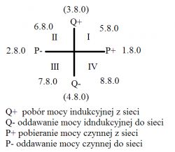
    Only how is it when we have inductive, both in production and in reception, and the same with capacitive, there are four quadrants and we have four indications of reactive energy 5.8.0, 6.8.0, 7.8.0 and 8.8.0 Which, of course, should be eliminated to what extent is it possible?
  • #19 19370767
    Tomkii
    Level 15  
    1.8.0 / 2.8.0 how much energy was effectively used (left side of the chart) / delivered to the grid (right side of the chart)
    5.8.0 / 7.8.0 how much inductive energy was used (1st square) [VAr+] / delivered to the grid (3rd square) [VAr-]
    6.8.0 / 8.8.0 how much capacitive energy was delivered (2nd square) [VAr+] / consumed from the network (4th square) [VAr-]
    As we produce (the active flow is TO the network), the reactive one is calculated at 6.8.x [VAr+] and 7.8.x [VAr-].

    We are not supposed to eliminate them in home conditions (when we are not billed for it) but to increase line losses just by their increase (in the case of voltage above 250V). When we are billed for reactive energy, the matter is not so obvious...
    And of course, if at night we have 250V in the socket, there is no other option than chasing the operator, because it will not be beaten in any way...
    
              +
              ^
       5.8.x  |  6.8.x
              |
    1.8.x  2.8.x
              |
       8.8.x  |  7.8.x
            
              -
    
  • #20 19370977
    Michał643
    Level 26  
    theo33 wrote:
    Only how it is when we have inductive and in production as well as when receiving and the same is with capacitive

    Well, simply: the meter sums up the reactive energy, distinguishing whether this energy was taken at P+ or at P-.
    5.8.0 - we downloaded X kvarh of reactive (inductive) energy from the network during active power consumption
    6.8.0 - we took X kvarh of reactive (inductive) energy from the network during the production of active power
    7.8.0 - we delivered X kvarh of reactive (inductive) energy to the grid during the production of active power
    8.8.0 - we delivered X kvarh of reactive (inductive) energy to the grid while taking active power from the grid

    theo33 wrote:
    Which, of course, can be eliminated?

    Overcoming 253V Voltage Limit in German Standards: VDR AR-N4105, BDEW, VDE 0126

    In order to lower the voltage, reactive power (inductive by default) should be taken, i.e. work in quadrants I or II. Therefore, the consumption of reactive power (Q+) should be maximized by setting the inverter operating mode with inductive cos phi.

    However, it should be noted that if we have a 3-phase system, it may happen that we take reactive power on one phase and give it out on the other. Then Q+ and Q- can light up simultaneously. Even all the arrows can light up at once, which shouldn't surprise anyone. Thus, the values of reactive power supplied and consumed can be simultaneously calculated in different registers of the meter, so this must be taken into account during some analyses.
  • #21 19371172
    Tomkii
    Level 15  
    And not in III? I won't cut my head off.
    The formula for delta U in a line = P/Un*R + Q/Un*X. To reduce the voltage Q we must go negative because the line has inductive reactance (X of +).
  • #22 19371226
    Michał643
    Level 26  
    Tomkii wrote:
    The formula for delta U in a line = P/Un*R + Q/Un*X.

    Okay, so from this formula, if Q is negative, we'll have this equation:
    1) dUfaz = P/Ufaz*R - Q/Ufaz*X
    and if Q is positive:
    2) dUfaz = P/Ufaz*R + Q/Ufaz*X
    It can be seen that the second voltage drop is greater than the first, so in the second case the voltage at the consumer is lower, because we have a higher voltage drop on the line. Will it be or not? (because I also notice that something is hard for me lately :) )

Topic summary

The discussion revolves around the issue of voltage exceeding 253V in Germany, particularly affecting users with photovoltaic (PV) systems. Participants suggest investigating the cause of the voltage increase, which may stem from the power grid or local network conditions. Several standards are mentioned, including VDR AR-N4105, BDEW, and VDE 0126, with a focus on how they relate to voltage management. Users express concerns about the impact of high voltage on household appliances and the need for solutions, such as adjusting inverter settings or contacting the utility provider (PGE) for voltage regulation. The conversation also touches on the importance of reactive power management to mitigate voltage issues and the potential for future regulations regarding inverter performance.
Summary generated by the language model.
ADVERTISEMENT