The importance of a charge controller in a photovoltaic system
Many users of photovoltaic systems, especially novices or do-it-yourselfers, are not familiar with the charge controller as a device in a photovoltaic system. Without it, the system works just as well, but with less efficiency, and in a short period of time, the average life of the batteries is decisively shortened. In this article, we will look at the main functions of a charge controller and its valuable uses.
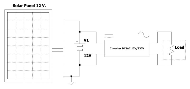
Circuit formed by solar panel, battery, inverter, and load
To fully understand the functionality of the charge controller, let us first examine a simple, low-power photovoltaic system consisting of the following components:
• a 12 V solar panel;
• a 12 V battery;
• an inverter (DC-AC 12 V to 230 V);
• a load.
At the moment, it is not essential to know the amount of current circulating in the circuit. What is important is to understand the basic concept. As can be seen from the diagram in Figure 1, the components are connected to each other using a general solution, which is widely used by users with a low to medium level of knowledge of electronics. The realization of such a solution is, however, not advisable at a stable, professional, and lasting level, as the system encounters many problems in its normal use. Let us now examine the two states of operation, i.e., the charging state of the battery (in the morning, in the presence of the sun) and the discharging state (in the evening, when the battery supplies the load but is not charged by the solar panel):
• In the morning, when the sun is shining, the solar panel generates a voltage that is certainly higher than that of the battery. The current therefore flows through the circuit and recharges the battery itself. Its voltage, of course, starts to increase more and more, but there is no control over either the amount of current delivered by the panel, or the voltage reached by the battery. If the light hitting the panel is excessive, the battery could even be damaged by overvoltage, overcurrent, or excessive temperature. In other words, there is no control over the charging mode, and for a good automated system, this is simply not acceptable. Furthermore, the cost of batteries (especially lithium batteries) is very high, so the user cannot allow a crude circuit, without any control system, to charge batteries in this simple but dangerous mode;
• In the evening, the solar panel produces no current, and its voltage is very close to 0 V. The battery voltage is much higher than that of the panel (usually 12.6 V), so most of the energy regularly feeds the inverter, but a significant fraction of it flows back through the solar panel. In some cases, the latter may be damaged.
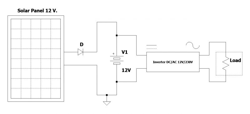
Circuit consisting of a solar panel, battery, inverter, load, and blocking diode
A first solution to the problem is to prevent current from flowing backwards by adopting a blocking diode, which can allow energy to flow from the solar panel to the battery but not vice versa. The diode to be used must withstand a current greater than that flowing through the battery during charging. Unfortunately, the diode is known to produce a voltage drop at its ends of about 0.6 V, so the voltage of the solar panel would be decreased by this factor, which is sometimes unacceptable. To remedy the problem, power Schottky diodes can be used, which offer a much smaller voltage drop. Figure 2 shows the principle diagram of a small solar system using a blocking diode connected between the solar panel and the battery. The solution of using the diode solves the problem of current return to the solar panel, especially at night or in very low external light conditions. However, the problem of charge control, both within the voltage and current limits, is not solved. This solution therefore only safeguards the integrity of the solar panel but not that of the battery.
The charge controller
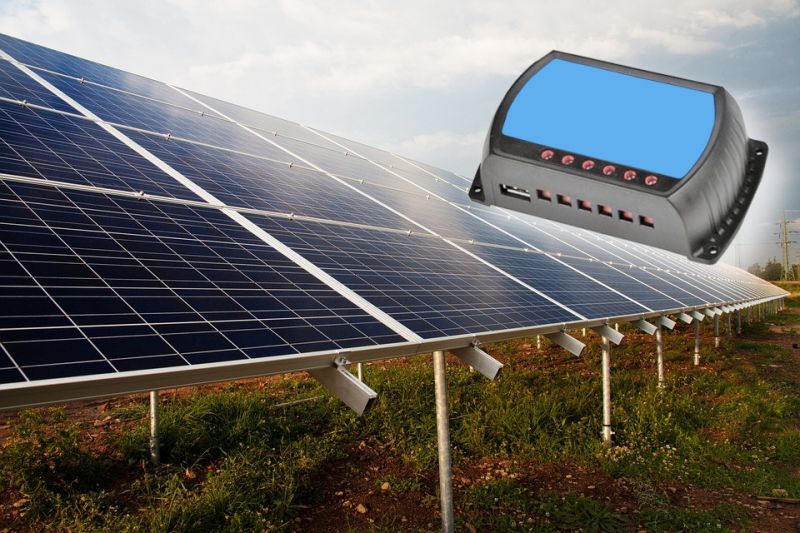
Also known as the "Solar Controller," it is an extremely important and indispensable device for the smooth operation of the photovoltaic system. It performs various functions, and, depending on the type of model used, it is possible to find controllers for all kinds of requirements at very different prices. The market also provides extremely low-cost models that do an excellent job. There are regulator models that operate in PWM and MPPT. One of the most important functions of this device is to use the electricity produced by the photovoltaic system to charge the batteries and prevent overcharging. It also reduces or interrupts the charging current when the batteries are charged, preventing the degradation of the precious accumulators. It therefore regulates the voltage and current supplied by the photovoltaic panel to values compatible with the specifications of the batteries used. The main function of a charge controller is to ensure a constant current on the load by intelligently drawing it from the solar panels and the battery. It also interrupts charging when the battery is fully charged and disconnects the load from the circuit when the battery is discharged, thus preventing overcharging or deep discharge of the battery. Its service life is therefore greatly extended, resulting in great savings for one's pocket and environmental protection. Even low-end charge controllers often use a microcontroller to manage all electrical and electronic operations. The minimum functions of a charge controller can be summarized as follows:
• It controls the charging of the battery, guaranteeing a correct supply of current to it;
• When the battery voltage approaches full charge, the device automatically interrupts the charging cycle;
• It controls and manages battery discharge as best it can;
• If the battery voltage is too low, the charge regulator immediately interrupts the supply to the load in order to over-discharge the battery, resulting in its degradation;
• It protects the circuits against polarity reversals, both of the load and the battery and the solar panel;
• It protects the system against accidental short circuits;
• It protects the system against different types of problems.
As can be seen, therefore, the work performed by the charge controller is extremely important, and it performs, in a fully automatic manner, many valuable functions that secure the various electronic components of the entire system. In this way, the user can also sleep soundly. Figure 3 shows the general wiring diagram with the four basic components, namely the charge controller, the solar panel, the battery, and, of course, the load(s). Respecting the correct polarities, the connections to be made are as follows:
• The solar panel is connected to the input of the charge controller, obviously respecting the maximum permitted voltages;
• The battery is connected to the central terminals of the charge controller;
• The load is connected to the output of the charge controller, respecting, of course, the maximum permissible voltages.
Note that loads can operate in direct current, e.g., at voltages of 12 V or 24 V. The load could also consist of an inverter (DC-AC) that converts the 12 V or 24 V DC voltage into 230 V or 115 V AC voltage. To avoid possible damage to the devices, the correct polarity of the connections between the devices must be strictly observed. Furthermore, the voltage of the solar panel must not exceed the maximum voltage tolerated by the charge controller, otherwise it may be damaged. Charge controllers in all market ranges have light indicators or LCD displays to show the information from the battery analysis. Thus, the user could read, for example, the regulator's current mode of operation (battery charging or discharging), the instantaneous voltage of the battery itself, and any messages or various warning indications.
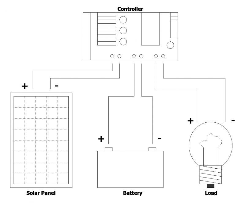
Figure 3: The generic connection diagram between the charge controller, the photovoltaic panel, the battery, and the load
PWM and MPPT charge controllers
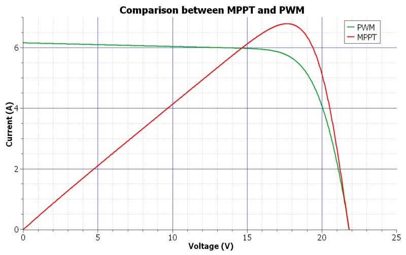
Both charge controller technologies can be used to charge batteries using energy produced by solar panels. The PWM controller is a switch that connects the solar panels to the battery. It reduces the voltage of the panels to the level of the batteries. The MPPT controller, on the other hand, is more sophisticated and expensive and always uses a microcontroller. It adjusts its input voltage in order to collect the maximum possible power from the solar panels and, therefore, transform the energy to return it to the optimum level for the battery. The graph shown in Figure 4 shows the course of the current in relation to the voltage.
A charge controller must first be chosen in relation to the environmental operating conditions and the desired electrical performance so that the maximum input current and the maximum output current do not exceed the controller's maximum capacity. In theory, it is possible to connect several identical controllers in parallel if the characteristics of a single model do not reach the required minimum. Some controllers allow the status of the main parameters to be read on the display during operation, but the cost, of course, is higher. A charge controller requires no special maintenance, but it should be installed away from direct sunlight and in a fairly ventilated and cool area. Theoretically, a charge controller could be realized with simple discrete components, but it is easy to see how a model equipped with a microcontroller is more reliable, smaller, and has more functionality.
Conclusions
When dimensioning a photovoltaic system, it is always advisable to foresee the worst-case operation of the system so as not to be unprepared when electrical or atmospheric conditions exceed maximum limits. The charge controller must also be purchased according to the type of battery used. If, for example, a charge regulator is designed for lithium batteries, it could not be used to regulate the charge of lead-acid batteries; otherwise, the batteries would be sure to degrade. Finally, the charge regulator should not be used when the energy of the solar panel is at least 60 times smaller than the energy produced by the battery. In this case, charging takes place in buffer mode without causing any damage to the accumulator.


