Motor Control in a Nutshell
Electric motors are practically ubiquitous since they are employed in so many different electronic applications. We have several examples in our homes, including fans, hair dryers, fan heaters, kitchen equipment, and more. When we turn our attention to cars, we quickly see that they have a variety of electric motors, including seat controls, electric windows, electric mirrors, radiator cooling fans, and more.
To deal with a motor control application, every designer, manufacturer, or student must understand the essential ideas that will be covered in this article.
Type of motors
The designer must choose a motor type from among those available in the market depending on the technical and financial requirements of the specific application. Brushed, brushless (which are further separated into BLDC and PMSM), induction, and stepper motors are the four basic types of motors.
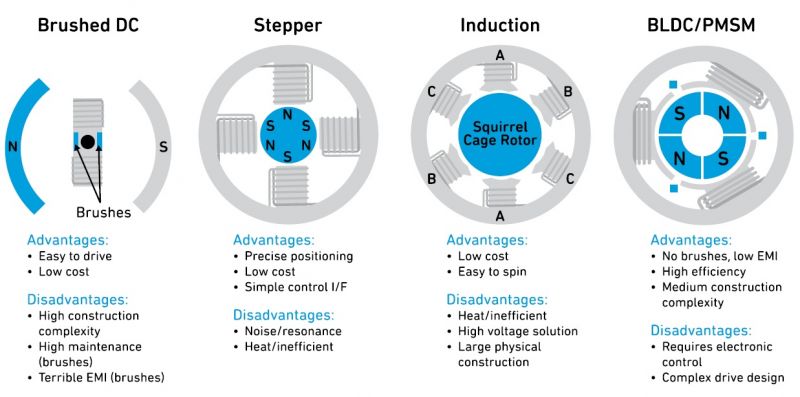
Figure 1 shows the four types of electric motors mentioned above, together with a list of the key benefits and drawbacks that each one offers.

Figure 1: The four main types of electric motor (Source: Motor Control Fundamentals for Dummies, Qorvo Special Edition)
The use of BLDC and PMSM motors, two closely related types of brushless motors, has increased for a range of applications. These motors are more efficient than brushed motors and have a substantially longer lifespan because they don't need brushes or a commutator.
Commutation, or the process of switching current flow in the phases to produce a rotating magnetic field and motion, is created via the brush/commutator interface in brushed motors. This interaction results in friction and arcing, both of which are undesirable.
To eliminate the brushes and commutator, BLDC motors and PMSMs use an electronically generated rotating magnetic field. External circuits created expressly for this purpose are used to modulate the voltages and currents supplied to the phases.
Contrary to traditional brushed motors, BLDC motors and PMSMs offer several advantages despite being more complicated. Their electronic commutation methods increase energy efficiency by 20% to 30% and are more reliable, more compact, lighter, and quieter than brushed motors operating at the same speed.
While the windings are positioned on the rotating rotor in brushed motors, they are located on the stationary stator in brushless motors (which is stationary). The arrangement of the permanent magnets and windings inside the electric motor eliminates the need for brushes. To regulate the current flowing to the stator coils of BLDC motors or PMSMs, an electronic controller is necessary.
BLDC and PMSM motors provide for fine speed control, are better suited for variable-speed applications, and have better speed vs torque characteristics than AC Induction motors.
The role of the motor controller
To ensure precise speed regulation, torque control, and efficiency optimization, BLDC motors and PMSMs both use electronic commutation, which necessitates a separate circuit to give the precise timing of coil energization.
Today, a single high-performance microprocessor that drives external (or internal, in some circumstances) high power MOSFETs is combined into this circuit. This device is also known as a motor controller. An integrated solution primarily offers two advantages:
• It simplifies the design of the motor drive circuit, moving the complexity inside the microcontroller
• It reduces the number of external components (BOM), which in turn involve lower costs.
The most important functions implemented in a motor controller are the following:
• Regulation of motor speed, torque, or power output
• Control of startup phase (soft start)
• Protection against circuit faults and overloads
• Acceleration and deceleration profile
Motor drive types
Synchronous motors include both BLDC and PMSM types. While the magnetic poles on the rotor try to synchronize and catch up, the commutation applied to the stator phases generates a rotating magnetic field. This causes the motor to start rotating, and it will keep doing so if the commutation is used.
When a current-carrying conductor is placed in a magnetic field or if the conductor cuts the magnetic field, electromotive force (EMF) is induced or produced in the conductor. Current can move via a closed path if it is open. The EMF produced in any motor as a result of motion is known as back-EMF because it opposes the EMF of the generator.
The stator winding geometry of BLDC and PMSM motors differs, which affects how they respond to back-electromotive force (BEMF).
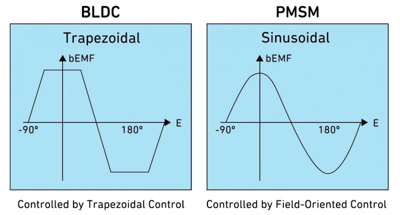
More specifically, BLDC BEMF responses are trapezoidal, whereas PMSM BEMF responses are sinusoidal. This is due to the sinusoidal coil winding of PMSMs, which produces a sinusoidal BEMF signature (which is very similar to three sinewaves phased 120° apart).
Trapezoidal and FOC controls
To achieve the sinusoidal waveform required to control the PMSM motor, a FOC (Field-Oriented Control) algorithm is used. FOC is a variable frequency control of the stator in a three-phase motor which uses two orthogonal components. One is the magnetic flux generated by the stator, while the other is the torque as defined by the speed of the motor determined by the rotor position.
BLDC motor control is easier, less complex, and less expensive than the PMSM motor control. The latter, however, achieves lower noise and fewer harmonics in the current waveform. Normally, BLDC motors perform better with a six-step trapezoidal algorithm, whereas PMSMs motors perform better with sine wave commutation algorithms.
Read the original article here.
Electric motors are practically ubiquitous since they are employed in so many different electronic applications. We have several examples in our homes, including fans, hair dryers, fan heaters, kitchen equipment, and more. When we turn our attention to cars, we quickly see that they have a variety of electric motors, including seat controls, electric windows, electric mirrors, radiator cooling fans, and more.
To deal with a motor control application, every designer, manufacturer, or student must understand the essential ideas that will be covered in this article.
Type of motors
The designer must choose a motor type from among those available in the market depending on the technical and financial requirements of the specific application. Brushed, brushless (which are further separated into BLDC and PMSM), induction, and stepper motors are the four basic types of motors.
Figure 1 shows the four types of electric motors mentioned above, together with a list of the key benefits and drawbacks that each one offers.

Figure 1: The four main types of electric motor (Source: Motor Control Fundamentals for Dummies, Qorvo Special Edition)
The use of BLDC and PMSM motors, two closely related types of brushless motors, has increased for a range of applications. These motors are more efficient than brushed motors and have a substantially longer lifespan because they don't need brushes or a commutator.
Commutation, or the process of switching current flow in the phases to produce a rotating magnetic field and motion, is created via the brush/commutator interface in brushed motors. This interaction results in friction and arcing, both of which are undesirable.
To eliminate the brushes and commutator, BLDC motors and PMSMs use an electronically generated rotating magnetic field. External circuits created expressly for this purpose are used to modulate the voltages and currents supplied to the phases.
Contrary to traditional brushed motors, BLDC motors and PMSMs offer several advantages despite being more complicated. Their electronic commutation methods increase energy efficiency by 20% to 30% and are more reliable, more compact, lighter, and quieter than brushed motors operating at the same speed.
While the windings are positioned on the rotating rotor in brushed motors, they are located on the stationary stator in brushless motors (which is stationary). The arrangement of the permanent magnets and windings inside the electric motor eliminates the need for brushes. To regulate the current flowing to the stator coils of BLDC motors or PMSMs, an electronic controller is necessary.
BLDC and PMSM motors provide for fine speed control, are better suited for variable-speed applications, and have better speed vs torque characteristics than AC Induction motors.
The role of the motor controller
To ensure precise speed regulation, torque control, and efficiency optimization, BLDC motors and PMSMs both use electronic commutation, which necessitates a separate circuit to give the precise timing of coil energization.
Today, a single high-performance microprocessor that drives external (or internal, in some circumstances) high power MOSFETs is combined into this circuit. This device is also known as a motor controller. An integrated solution primarily offers two advantages:
• It simplifies the design of the motor drive circuit, moving the complexity inside the microcontroller
• It reduces the number of external components (BOM), which in turn involve lower costs.
The most important functions implemented in a motor controller are the following:
• Regulation of motor speed, torque, or power output
• Control of startup phase (soft start)
• Protection against circuit faults and overloads
• Acceleration and deceleration profile
Motor drive types
Synchronous motors include both BLDC and PMSM types. While the magnetic poles on the rotor try to synchronize and catch up, the commutation applied to the stator phases generates a rotating magnetic field. This causes the motor to start rotating, and it will keep doing so if the commutation is used.
When a current-carrying conductor is placed in a magnetic field or if the conductor cuts the magnetic field, electromotive force (EMF) is induced or produced in the conductor. Current can move via a closed path if it is open. The EMF produced in any motor as a result of motion is known as back-EMF because it opposes the EMF of the generator.
The stator winding geometry of BLDC and PMSM motors differs, which affects how they respond to back-electromotive force (BEMF).
More specifically, BLDC BEMF responses are trapezoidal, whereas PMSM BEMF responses are sinusoidal. This is due to the sinusoidal coil winding of PMSMs, which produces a sinusoidal BEMF signature (which is very similar to three sinewaves phased 120° apart).
Trapezoidal and FOC controls
To achieve the sinusoidal waveform required to control the PMSM motor, a FOC (Field-Oriented Control) algorithm is used. FOC is a variable frequency control of the stator in a three-phase motor which uses two orthogonal components. One is the magnetic flux generated by the stator, while the other is the torque as defined by the speed of the motor determined by the rotor position.
BLDC motor control is easier, less complex, and less expensive than the PMSM motor control. The latter, however, achieves lower noise and fewer harmonics in the current waveform. Normally, BLDC motors perform better with a six-step trapezoidal algorithm, whereas PMSMs motors perform better with sine wave commutation algorithms.
Read the original article here.


