logo elektroda
logo elektroda
X
logo elektroda

Confirming Resistor Value for R52 on Domotic SMP192-02 Converter

Mikomatik 450 5
ADVERTISEMENT
  • #1 21351001
    Mikomatik
    Level 2  
    Hi,
    In the process of fixing a Domotic SMP192-02 converter which has an open R52.
    Seems to be 47kohm but I would like a confirmation about this value.
    It would be very grateful if anybody can help.
    My best.

    Mike
    AI: Do you have access to any service manuals or schematics for the Domotic SMP192-02 converter that might confirm the resistor value for R52?
    No
    AI: Are there any visible markings or color bands on the resistor that could help verify its value?
    No
  • ADVERTISEMENT
  • Helpful post
    #2 21351281
    dt1
    Admin of Computers group
    Hello,
    I found this thread about a similar device, but this answer is about SMP192-02 model: https://www.elektroda.pl/rtvforum/topic3909700.html#20160271

    It says the resistor is 10Ω 1%.

    There is another thread with nice close ups of the PCB: https://www.elektroda.pl/rtvforum/topic3471990.html - it seems that R52 is burnt, but most strips are recognizable.
  • ADVERTISEMENT
  • #3 21352445
    Mikomatik
    Level 2  
    Many thx DT1,
    I made a typo mistake about the resistor reference: in fact I need to confirm R2 (47 kΩ?), not R52 (which is effectively 10Ω).
    By the way in post 20160271 Marcin_03136 gave a wrong value for R8: the right value is 220Ω not 220 kΩ.
    I made a reverse engineering of the full device and redrew the schematics (main board 2 modules). I'm not familiar with this forum, is there a way to upload the files (Kikad V8.x) onto a correct folder?
    Mike
  • ADVERTISEMENT
  • #4 21352849
    dt1
    Admin of Computers group
    The R2 can't be seen on photos, it must be behind some other component. On another board I found info that this may be a 470k resistor. This is based on info from another Dometic SMP unit, but they seem to share a lot.

    Also, I found a very low quality and poor colour rendering photo of this resistor, burnt, but there is still something visible. Manual colour correction of white balance still does nothing useful with this photo.

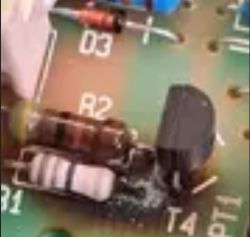
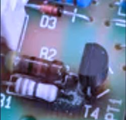
    Circuit board with visible resistor R2 with colored bands and other components. Close-up of a circuit board with a resistor labeled R2 and other electronic components. .

    This is likely a 5-bar resistor, so it goes like yellow, violet, black. The question is if the fourth strip looks rather orange or red. Orange would be 470k and red would be 47k. Maybe someone with a similar board can check.

    Nice work with drawing the schematics. If you would like to share, you can do it in this topic. The file attachment is possible in a full editor (so you should click on the answer button under the last post in a thread and not use the box where you can post a quick reply). You can look in https://www.elektroda.pl/rtvforum/topic3815619.html - this topic is for something else, but around the middle there is a spoiler and in this spoiler it is shown how to attach files. It is in Polish, but should be translator-friendly :)

    If you get an error of unsupported extension, please use zip/rar/7z compression, these compressed files are accepted, so this should fix a problem if it happens.
  • ADVERTISEMENT
  • #5 21353201
    Mikomatik
    Level 2  
    Full schematics of the Dometic SMP192-02 under Kikad V8.x (see attached zip file) including:
    - Mother Board
    - Oscillator Module
    - Relay Control Module

    To be determined/done:
    - Type and section of ferrite used for transformer TR1, diameter of copper wires and number of loops for the primary and secondary windings.
    - Same for inductance L3.
    - Function of toroid L3 in series with the primary section of transformer TR1.
    - Determination of type and value of component labeled FB in base of Q2 in Oscillator Module (assumed it's a ferrite bead but unsure of this).
    - Value of common mode inductor CM_Ind on Mother Board.
    - Correction/improvement of schematics.

    Enjoy!
  • #6 21355143
    Mikomatik
    Level 2  
    I guess I need to open a new post regarding the schematic as the current post title is not attractive to those who need some information to fix their own devices.
    For information, fuse F1 is a 5A 250V slow-blow encapsulated in a ceramic package. I will update the Mother Board schem if a new post should be open.
    My best,
    Mike
ADVERTISEMENT