FAQ
TL;DR: ESP32 runs at 3.3 V, and "SDA - default GPIO21, SCL - default GPIO22." If your I2C LCD is blank, set those pins in code and adjust contrast to fix it when migrating Arduino RPM counters to ESP32. [Elektroda, iftri, post #21416080]
Why it matters: This FAQ helps ESP8266/ESP32 builders fix no‑display and counting issues when using A3144/LM393 Hall sensors and I2C LCDs for RPM.
Quick Facts
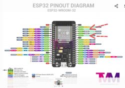
- ESP32 default I2C pins: SDA=GPIO21, SCL=GPIO22; logic level is 3.3 V. [Elektroda, iftri, post #21416080]
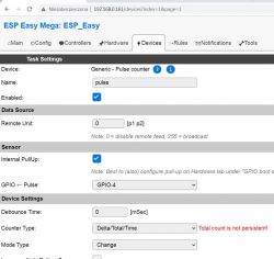
- ESP8266 example: Hall on GPIO4 (D2), sampleTime=1000 ms, LCD I2C=0x27, Serial=115200 baud. [Elektroda, iftri, post #21404166]
- Choose either an Arduino .ino or ESPEasy Rules; do not mix both. [Elektroda, starob, post #21416663]
- ESPEasy Tools > Interfaces > I2C Scanner quickly confirms your LCD’s I2C address. [Elektroda, starob, post #21416752]
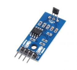
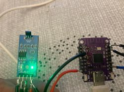
- LM393 Hall module D0 toggles with magnet; connect D0 to a GPIO to count RPM. [Elektroda, sznickers, post #21418217]
Can I run an Arduino A3144 RPM sketch on ESP8266/ESP32 without ESPEasy?
Yes. Set up Arduino IDE for ESP8266/ESP32, select your board, and upload the .ino over USB. This bypasses ESPEasy entirely. The thread confirms uploading to ESP32 from Arduino IDE after installing the ESP32 platform. Open the IDE, choose the correct COM port, and flash. Then wire the Hall sensor and LCD as the sketch expects. Check Serial Monitor to verify counts. [Elektroda, iftri, post #21416795]
Why does my I2C LCD stay blank on ESP32?
ESP32 is 3.3 V logic. Many LCD backpacks expect 5 V power, so confirm supply and contrast. Set I2C to the default pins in code: SDA=GPIO21 and SCL=GPIO22. Recheck cabling and polarity. The helper specifically called out pins 21/22 and contrast during troubleshooting. This fixes most “blank screen” cases when migrating. [Elektroda, iftri, post #21416080]
Do I need pull‑up resistors on I2C for ESP boards?
Yes. I2C requires pull‑ups on SDA and SCL. Internal pull‑ups may work, but external ones improve reliability. First, bring up the display with a simple Arduino demo to prove wiring and pull‑ups. After that, proceed with ESPEasy or your sketch. This sequence reduces false negatives during debugging. [Elektroda, starob, post #21416730]
How do I wire an LM393 Hall module to ESP and verify it works?
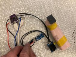
Power the module, then connect D0 to a chosen GPIO. Spin the magnet and watch the onboard DOUT LED. The poster confirmed working RPM counts after wiring D0, with the LED blinking during rotation. If the LED never blinks, the sensor isn’t detecting passes. Confirm wiring and continue testing. [Elektroda, sznickers, post #21418217]
How is RPM calculated in the provided ESP code?
The sketch samples for 1000 ms, counts pulse edges, then multiplies by 60 to get RPM. It sets the Hall pin as INPUT_PULLUP and uses an LCD at address 0x27. Serial logging runs at 115200 baud. Edit sampleTime to balance responsiveness and stability. One pulse corresponds to one revolution by default. [Elektroda, iftri, post #21404166]
How do I send RPM readings to Domoticz from an ESP?
Use HTTP GET to Domoticz’s udevice endpoint. Format: /json.htm?type=command¶m=udevice&idx=YOUR_IDX&nvalue=0&svalue=RPM. The example transmits every 5 seconds with ESP8266HTTPClient. Replace idx with your device index and set your Domoticz IP:8080. Check returned HTTP code to confirm delivery. [Elektroda, iftri, post #21404166]
Why won’t my Arduino code run inside ESPEasy Rules?
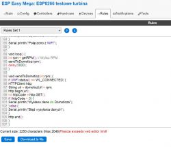
ESPEasy Rules is a separate interpreter, not C++. Upload the sketch directly instead. As one expert noted, “Uploading it to rules won’t work.” Use either a pure .ino or ESPEasy with proper Rules, not both together. Mixing approaches leads to failure. [Elektroda, starob, post #21416796]
How do I check my I2C LCD with ESPEasy before coding?
Open ESPEasy, go to Tools > Interfaces > I2C Scanner. It lists detected I2C addresses, confirming the LCD responds. If the LCD appears, wiring and pull‑ups are likely correct. If not, recheck power, SDA/SCL, and cable integrity before changing code. This saves time. [Elektroda, starob, post #21416752]
What does the “Time” knob on my LM393 board do? Do I need it?
A user reported success without touching the “Time” setting. Correct magnet alignment relative to the sensor fixed their issue. If readings stall, prioritize spacing and orientation first. Only tweak the board after alignment feels solid. This matched their working setup. [Elektroda, sznickers, post #21406001]
Which I2C pins should I set in ESP32 code?
Use GPIO21 for SDA and GPIO22 for SCL. Call Wire.begin(21, 22) or configure your LCD library accordingly. As a reminder, “These pins are the default.” Setting them explicitly prevents silent configuration mismatches. This step resolves many display problems. [Elektroda, iftri, post #21416629]
How do I build a basic ESP RPM counter in 3 steps?
- Wire the Hall module: D0 to GPIO (ESP8266 D2/GPIO4), plus VCC and GND.
- Open the provided sketch in Arduino IDE, select your ESP board and port, and upload.
- Open Serial at 115200 baud, then tune sampleTime and confirm LCD address 0x27.
[Elektroda, iftri, post #21404166]
My RPM stays at zero. What should I check first?
Check the module’s D0 LED during magnet passes. If it never blinks, the sensor isn’t triggering. After wiring D0 to a GPIO, the poster reported successful counting. Verify the signal path and repeat the magnet test until the LED indicates detection. [Elektroda, sznickers, post #21418217]
Can I change sample time or baud rate for responsiveness?
Yes. The example uses sampleTime=1000 ms and Serial at 115200 baud. Lower sampleTime for faster updates, or raise it for smoothing. Keep the RPM multiplier aligned with your sampleTime change. Tuning both parameters improves readability without sacrificing accuracy. [Elektroda, iftri, post #21404166]
Which GPIO should I use for the Hall sensor on ESP8266?
The example uses GPIO4, labeled D2 on many ESP8266 boards. Configure it as INPUT_PULLUP and connect the module’s D0 there. This matched the working code path shared. Verify your board’s pin labels and test with a magnet. [Elektroda, iftri, post #21404166]
