I am working on measuring the actual spindle speed on a small CNC machine tool.
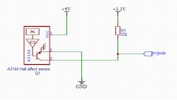
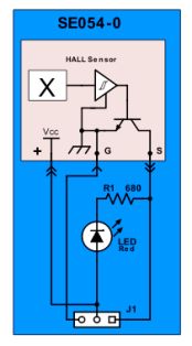
The module is a WiFi Lora 32 V2 (https://heltec.org/project/wifi-lora-32/). The HAL sensor is a Waveshare AH49E module - https://botland.com.pl/pl/czujniki-pradu/4494-czujnik-halla-ah49e-modul-waveshare.html, module diagram - https://www.waveshare.com/w/upload/2/28/Hall-Sensor-Schematic.pdf. Arduino IDE.
For testing, I prepared a trivial code: For one second, the interrupts are to count pulses from the digital output of the Waveshare Hall AH49E module (it has both analogue and digital outputs). Then, I turn off the interrupts and display the number of counted pulses. In the target program, I will count the RPM. To start with, the number of pulses per second is enough for me.
To check how the code works, I connect a signal from a rectangular waveform generator to the module input. The signal has a frequency of a few hundred Hz. This is a frequency close to that which will be given by the sensor mounted on the spindle. The code works perfectly. By varying the frequency from the generator I can measure "speed" from a few hundred to a few tens of thousands of RPM without any problem. Beautifully.
Unfortunately beautiful is not. The problems start when, instead of the generator, I connect a HAL sensor to the ESP 32 (GPIO 17).
I made two attempts with the same sad result:
1) The sensor is attached close to a magnet glued to the fan wings from the PC.
2) The sensor mounted near the CNC spindle
The results shown by the software are highly variable. They vary from second to second, e.g. between 780 and 1140 pulses counted in one second, despite the apparently constant speed of the fan or spindle. I would still be able to believe that the fan rotates unevenly, but the inverter-controlled spindle rather has a constant speed. The amplitude of the signal from the generator and the HAL module is the same.
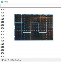
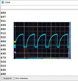
My toy oscilloscope shows that the signal rises slowly but falls quickly.
I attach two images. One shows the results on the Arduino IDE console for the rectangular waveform and the waveform itself on the screen of my toy oscilloscope, the other shows the results plotted every second when the HAL sensor is connected to the ESP and the waveform from the digital output of the HAL sensor module. Even on the oscilloscope screen the frequency readout is not constant.
Can anyone help? Where could the error be? I don't like the shape of the "digital" signal from the sensor module. Maybe move this post to some other forum closer to electronics ie Hal sensor.
 .
.
----------- Code -----------
int hallsensor = 17;
volatile long ticks = 0;
void pick() {
ticks++;
}
void setup() {
Serial.begin(9600);
pinMode(hallsensor, INPUT_PULLUP);
attachInterrupt(digitalPinToInterrupt(hallsensor), pick, FALLING);
}
void loop() {
delay(1000);
sei();
Serial.println(ticks);
ticks=0;
cli();
}
--------------
The module is a WiFi Lora 32 V2 (https://heltec.org/project/wifi-lora-32/). The HAL sensor is a Waveshare AH49E module - https://botland.com.pl/pl/czujniki-pradu/4494-czujnik-halla-ah49e-modul-waveshare.html, module diagram - https://www.waveshare.com/w/upload/2/28/Hall-Sensor-Schematic.pdf. Arduino IDE.
For testing, I prepared a trivial code: For one second, the interrupts are to count pulses from the digital output of the Waveshare Hall AH49E module (it has both analogue and digital outputs). Then, I turn off the interrupts and display the number of counted pulses. In the target program, I will count the RPM. To start with, the number of pulses per second is enough for me.
To check how the code works, I connect a signal from a rectangular waveform generator to the module input. The signal has a frequency of a few hundred Hz. This is a frequency close to that which will be given by the sensor mounted on the spindle. The code works perfectly. By varying the frequency from the generator I can measure "speed" from a few hundred to a few tens of thousands of RPM without any problem. Beautifully.
Unfortunately beautiful is not.
I made two attempts with the same sad result:
1) The sensor is attached close to a magnet glued to the fan wings from the PC.
2) The sensor mounted near the CNC spindle
The results shown by the software are highly variable. They vary from second to second, e.g. between 780 and 1140 pulses counted in one second, despite the apparently constant speed of the fan or spindle. I would still be able to believe that the fan rotates unevenly, but the inverter-controlled spindle rather has a constant speed. The amplitude of the signal from the generator and the HAL module is the same.
My toy oscilloscope shows that the signal rises slowly but falls quickly.
I attach two images. One shows the results on the Arduino IDE console for the rectangular waveform and the waveform itself on the screen of my toy oscilloscope, the other shows the results plotted every second when the HAL sensor is connected to the ESP and the waveform from the digital output of the HAL sensor module. Even on the oscilloscope screen the frequency readout is not constant.
Can anyone help? Where could the error be? I don't like the shape of the "digital" signal from the sensor module. Maybe move this post to some other forum closer to electronics ie Hal sensor.

 .
.
----------- Code -----------
int hallsensor = 17;
volatile long ticks = 0;
void pick() {
ticks++;
}
void setup() {
Serial.begin(9600);
pinMode(hallsensor, INPUT_PULLUP);
attachInterrupt(digitalPinToInterrupt(hallsensor), pick, FALLING);
}
void loop() {
delay(1000);
sei();
Serial.println(ticks);
ticks=0;
cli();
}
--------------


