logo elektroda
logo elektroda
X
logo elektroda

5V project power supply from AA batteries, L7805ABV and Feetech F5109M servo - schematic verificatio

Mabel123 330 19
ADVERTISEMENT
Treść została przetłumaczona polish » english Zobacz oryginalną wersję tematu
  • #1 21569988
    Mabel123
    Level 2  
    Hi!
    I am putting together a project that needs to work in the field for as long as possible. The batteries need to be easily accessible, so I have decided on AA batteries. I have ensured that all components can be powered by 5 volts. I would very much appreciate your review of the design in the appendix and any suggestions you may have. I am particularly concerned with the power supply, I have never done anything like this:
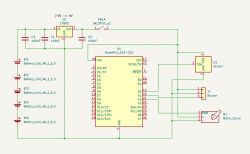
    Circuit diagram for powering NodeMCU ESP-32S, servo, sensor, and buzzer with five AA batteries and an L7805 voltage regulator. .

    100 nF ceramic capacitors, because that's what I have. The servo is a Feetech F5109M standard. The stabiliser is a 5 volt L7805ABV. If I understand correctly, I could add another battery there to increase the length of the project. Warm regards!
  • ADVERTISEMENT
  • #2 21570011
    Mateusz_konstruktor
    Level 36  
    Mabel123 wrote:
    As far as I understand, I could add another battery in there to increase the runtime of the project.
    .
    A simpler way to increase the runtime would be to replace the current voltage stabiliser with a low-dropout model.

    The issue with the battery voltage, on the other hand, is that as it depletes, the voltage is reduced.
    Here, at least one more cell would have to be added.
    The whole thing is up for reconsideration in this respect.
  • ADVERTISEMENT
  • #3 21570018
    Przemcio
    VIP Meritorious for electroda.pl
    If every mA in the field counts, it might be worthwhile instead of the L7805 to
    think about a low dropout voltage regulator?

    Maybe there would be some information on the difference in
    current consumption and that would be something!
  • ADVERTISEMENT
  • #4 21570271
    Mabel123
    Level 2  
    I understand, ie:
    - add one more AA battery in series, there will be six of them there,
    - replace the L7805ABV stabiliser with an LDO, for example the LDO 5 V LM1117T-5.0.

    An LDO regulator is basically the same as an LDO stabiliser, just with adjustable output voltage, yes? I need a constant 5 V, also I think I would stay with a regular stabiliser.
  • #5 21570281
    viayner
    Level 43  
    Hello,
    LDO means that we have a small voltage drop on the regulator circuit itself, for the LM7805 it is about 2 V, the LM1117 requires about 1 V (minimum difference between input and output). Linear produces for example the LT30xx series where this is in the order of 200-300 mV.
    Consider maybe an inverter, then the circuit will still work with a considerable voltage drop, well there comes the efficiency of this inverter. It is not a bad idea to separate the power supply for the control system (ESP) and the actuator (servo).
    Regards
  • #6 21570332
    waltersalata
    Level 23  
    How much current does the servo draw? How much heat will be given off to the 7805 - count it.
  • #7 21570829
    Mabel123
    Level 2  
    Quote:
    Consider maybe an inverter, then the circuit will still work with a considerable voltage drop, well there comes the efficiency of this inverter.


    I have never used an inverter before. Would it simply be a replacement for a stabiliser? I see something like a step-down converter to 5 volts. It definitely has a higher maximum current draw than a stabiliser.

    Quote:
    It is not a bad idea to separate the power supply for the control (ESP) and the actuator (servo).
    .

    When the voltage goes below 5 volts, the whole circuit will stop functioning anyway, so there may not be much point in splitting it. As soon as any component gets too low voltage, the whole circuit needs a battery replacement.

    Quote:
    How much current does the servo draw? How much heat will the 7805 give off.Count it.
    .

    Good question. I did not find a resistance for the stabiliser. I also couldn't find the current draw range of the Feetech F5109M servo unfortunately. I would have to physically test the servo under load and possibly select a stabiliser with a higher maximum output current. Assuming or making sure that overall the circuit will not exceed 800 mA, which is the maximum current of the LDO 5 V LM1117T-5.0 stabiliser, then I guess it should not overheat.
  • #8 21570886
    Przemcio
    VIP Meritorious for electroda.pl
    Mabel123 wrote:
    I also unfortunately did not find a current draw range for the Feetech F5109M servo
    .

    Mr Fellow - it is usually difficult to find documentation for something that is not there.
    This servo is most likely FS 5109M because this can be seen even in the photos on the internet at the
    companies selling it.

    See Link .

    I wonder what Uncle Google has in mind when he writes "contact current" - 1.7A - 6V?

    As for the L7805 you would perhaps need to see in the documentation
    what this heat release looks like.
  • ADVERTISEMENT
  • #9 21570925
    Mabel123
    Level 2  
    Quote:
    This servo is most likely the FS5109M, as this can be seen even in the photos on the internet of companies selling it.


    Facts. I found that it has a current draw in the range of 6 mA to 1.7 A, so such a simple linear stabiliser is out of the question. Thanks also to the previous responders for pointing out this heat.

    Quote:
    What about the L7805 then maybe in the documentation you would need to see what this heat release looks like.
    .

    Thank you for your attention! I've done a bit of reading and, however, a step-down inverter at 5 V sounds like the ideal solution. It has a high maximum output current, for example 3 A, it doesn't heat up, it has less losses, meaning longer circuit life.
  • #10 21571494
    gps79
    Level 36  
    And I would do things differently.
    I would power the whole thing from 4x1.5V. The nodemcu board has two ams1117 3.3V and 5V regulators in it, each can give 1A of current.
    I would power the servo directly from the battery and the rest from the existing regulators. Of course, the author hasn't given all the details of the components he will connect, because why should he?

    As if one were to approach the subject professionally, one would have to put the processor to sleep for downtime and put to sleep or disconnect the power supply from the other components by software.
  • #11 21571506
    Przemcio
    VIP Meritorious for electroda.pl
    gps79 wrote:
    I would power the camera directly from the battery


    Aha! I also thought about this option so as not to pack stabilisers for high current.

    This sleep is worth considering and BTW - the circuit has an ADC but will it be able to measure
    "own" supply voltage before the stabiliser?
    There would be a Battery Low signal e.g. on a 2mA LED because there are some. ;) .
  • #12 21572367
    Mabel123
    Level 2  
    Quote:
    Of course the author has not given all the details of the components he will connect, because why should he?
    .

    I'm wondering about the HC-SR501 PIR sensor. It needs to run on 5 volts like the rest of the components and have a range of 5m. I was also wondering about the Seeedstudio 101020793 sensor, but I would have to learn how to connect it bypassing the Grove system overlay.

    The buzzer is an Iduino ST1143, for example.

    Quote:
    I'd power the servo directly from the battery and the rest from existing controllers.
    .

    As far as I have read, the NodeMCU ESP-32S feeds 3.3 volts from its pins, meaning it could not power the sensor and buzzer, which need 5 volts.

    Quote:
    If one were to approach the subject professionally, one would have to put the processor to sleep for downtime and put or disconnect the power to the other components by software.


    The sensor is supposed to work all the time, so putting it to sleep is unnecessary. Likewise with the processor. Unless I misunderstand the concept of putting it to sleep.

    Putting the buzzer and servo to sleep might make sense. I understand that this would involve connecting their VINs via a transistor controlled by the controller, yes? Since a stationary servo and a non-writing buzzer don't use much power, it would have a noticeable effect on current consumption?

    Quote:
    There would be a Battery Low signal e.g. on a 2 mA LED because there are some.
    .

    I was thinking of using a LM2596 converter . How do you get the information that the voltage before the inverter is below some level, in this case 5 volts - the minimum drop across the inverter?
  • #13 21572390
    gps79
    Level 36  
    The PIR draws a relatively large amount of current. The whole thing probably won't be suitable for battery power (the operating time will come out to about 1 day on a set of alkaline batteries), so there's nothing to pin down on optimisation.
    I suggest you list what components the whole system will be made of, determine their power consumption and do an energy balance. From this, the energy requirements will come out.
    Without a picture of the whole, you will have to change the concept every now and then as you add requirements as to the shape of the device.
  • #14 21576457
    Mabel123
    Level 2  
    Quote:
    I will list what components the whole system will be made of, determine their power consumption and do an energy balance. From this the energy requirements will come out.
    .

    Components I would like to use along with the power consumption found:
    - NodeMCU ESP-32S - approximately 80 mA
    - Feetech FS5109M servo - 6 mA to 1.7 A
    - PIR sensor HC-SR501 - approx. 0.6 mA
    - Iduino ST1143 buzzer - approx. 30 mA

    The ESP-32S NodeMCU will not use WiFi or Bluetooth, but will work all the time. I anticipate that the servo will run at full power consumption for about 30 s per day. The signal received from the sensor will be every 5 s. The buzzer will also only run a few seconds per day. All in all, as far as I can count it correctly, it comes out to about 175 mA.

    Go ahead and suggest replacements if I have chosen some grandfathered components. Everything must run on 5 V, the servo must have a torque of about 10 kg-cm, the motion sensor must see a minimum of 5 m. NodeMCU ESP-32S I already have in stock.
  • #15 21576516
    Przemcio
    VIP Meritorious for electroda.pl
    A small correction regarding the current consumption of the HC-SR501 motion detector - 50uA is the current
    50uA is the resting current and a little more during operation.

    The device is supposed to operate in a closed room as I understand it.

    At the design stage, no offence, you have to fiddle around a bit with everything
    so that everything is clear from A to Z. You can see for yourself that not everything
    everything is described at the time of purchase and you have to do a bit of research so that there are no
    unpleasant surprises or other disappointments.
  • #16 21576530
    Mabel123
    Level 2  
    Ah, now I see, PIR sensor HC-SR501 - about 60 mA during operation. So all in all about 235 mA.

    The device is intended to operate outdoors.

    Please feel free to attach :D .

    Edited: An AA battery is approximately 2500 mAh. Six of these will be 15000 mAh and 9 volts. The 5 volt inverter, if I understand it correctly, will stop working when the voltage from the battery goes down to 5 volts. How do you calculate when this will happen? From the ratio I came up with around 27 h at 250 mA draw.
  • #17 21576619
    gps79
    Level 36  
    At different voltages, mA (or mAh) are not comparable. The balance must be done in units of energy (voltage x current), e.g. watt-hours [Wh].
    Devices consume 5V * 235mA = 1.175W.
    Assume that the voltage converter will have a loss of 20%, so the power drawn from the battery will be 1.175W + 20% = 1.41W.

    You build a 9V battery (6 2500mAh cells connected in series). The battery is 2.5Ah at 9V, so 22.5Wh.
    A 22.5Wh battery charged at 1.41W will give out energy for 22.5Wh / 1.41W = 16h.

    I suggest changing to a sensibly sized battery.
  • #18 21576641
    Przemcio
    VIP Meritorious for electroda.pl
    Mabel123 wrote:
    Please feel free to tag along
    .

    Do not provoke ! ;)

    The ESP-32S alone draws up to 260mA depending on the mode of operation.

    If this is to work outdoors then think about
    an airtight housing with a transparent cover for the PIR.
    cover for the PIR. But this may limit its range.
    Modules for Arduino, ESP and the like are unlikely to be
    intended for use in harsher than "room" conditions
    unless the manufacturer has stipulated otherwise.

    Well, and there will be some testing and calculations but this is how the device is made!

    Mabel123 wrote:
    A AA battery is about 2500mAh. Six of these will be 15000mAh and 9V.


    Rather, it will continue to be 2500mA and 9V. But on standby milliamps will be needed as long as the PIR is not too
    sensitive to "mosquitoes".

    Colleague gps79 rightly suggests a battery.
    And if it's going to work outside then maybe some recharging
    from micro solar panels?
  • #19 21577162
    Mabel123
    Level 2  
    Super! Thank you very much for explaining how to calculate this energy balance.

    As a first iteration, I will prepare the device on batteries. 16 h will allow to estimate if the construction makes sense at all. If everything goes bold, I think I'll be tempted to go for that battery, maybe even solar panels. The battery pack is a big enough expense that I'd like to test the minimum version first. Repowering from battery to battery shouldn't be a problem, since it'll go through the inverter anyway.
  • #20 21577205
    Mateusz_konstruktor
    Level 36  
    Here, there is no need to build according to one's own imagination and then find organoleptic failures that are easy to predict.
    Let us start with the question of servo current consumption.
    What is the maximum current, particularly at start-up?
    Here, the phenomenon of a momentary heavy load on the battery and a consequent drop in the supply voltage is to be expected.
    The end result can be various hang-ups and restarts, and what may be one of the biggest challenges of this project.
ADVERTISEMENT