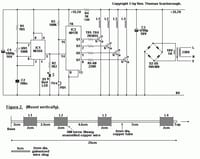
Did you find this schematic chisled on a clay tablet in a museum somewhere? The basic concept makes sense, but the implementation is from the stone age, like the mid 1970s.
It looks like IC1 is being used as a oscillator, and IC2 as a counter/decoder, but I didn't look up either. Presumably when FIRE is pressed, each of the outputs Q1, Q3, Q5, and Q7 go on in sequence for one count with one count of dead time between each. 2N3055 are big and slow and don't have much gain, but should work although there are better choices available today.
The biggest problem is how exactly the "+13.2V" is guaranteed to be that. It looks like R4 is simply a dropping resistor and the current draw on the 13.2V rail is counted on to drop the voltage accross this resistor from the 25.2V input supply. That's a really bad idea. The fact that the author specified voltages to three digits when they're probably within 10% on a good day should be a hint that maybe the best design process weren't employed.
Another very serious problem is there are no catch diodes or snubbers on the coils. 2N3055 can handle around 80V if I remember right (it's been a long time since I used one of those). That's a lot more than the 25V supply, but the coils could easily kick back more than that when switched off. I'm guessing this works only because the 2N3055 will turn off somewhat slowly, and are generally robust enough that the excessive voltage is leaked off without too much damage most of the time. Not a good idea.
As for the exact size of wire, different sizes will work but you will get different inductances and therefore current rise times, voltage kickbacks, and of course magnetic field strength to propell the projectile. It will take some experimentation to find the right timing for each coil.
If I was doing this today, I'd replace the logic with a single microcontroller that does the timing in firmware. I'd also create a real regulated supply for the micro. With 25V in, you can use a brute force 7805 regulator. It will get warm, but should be able to handle the average current. I'd probably use NPN power transistors as the original design did, but you don't need something with such large power dissipation. Each transistor will only be on for a short time. It would be good if they were rated for a few amps and around 80-100V so that you can design the snubbers to turn off the coils quickly. Nowadays you can find such transistors with better gain, especially since you don't need the power dissipation of a TO-3 package. There should be plenty of suitable choices in TO-220 or similar packages.


