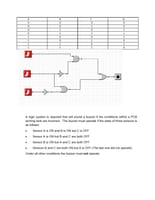
The problem is that you haven't implemented what's in your truth table.Let's go through this from the top -- the buzzer will be on if any of the following conditions are met, otherwise it will be off:#1 Sensor A is ON, B is ON, C is OFF#2 Sensor A is on, but B and C are both OFF#3 Sensor B is ON, but A and C are both OFF#4 Sensors B and C are ON, but A is OFF
Now let's look at the truth table (the one in your attachment) which shows the following:A B C Q0 0 0 0
0 0 1 0
0 1 0 1 (#3)
0 1 1 1 (#4)
1 0 0 1 (#2)
1 0 1 0
1 1 0 1 (#1)
1 1 1 0So far, so good -- this matches up with the text conditions. Now let's use the truth table as a basis for writing the Boolean equations. Note that I use '&' = AND, '|' = OR, and '!' = NOT
#3 #4 #2 #1
Q = (!A & B & !C) | (!A & B & C) | (A & !B & !C) | (A & B & !C)
So now we have to perform standard minimization techniques -- in this case I'd use a Karnaugh map (note that we organize the AB values in such a way as to implement a Gray code).
AB 00 01 11 10
C
0 0 1 1 1
1 0 1 0 0
Since I can't draw on this here, let's gather the 1s into two groups as shown below:
AB 00 01 11 10
C
0 0 * # #
1 0 * 0 0Look at the two '*' characters (these represent (#3 and #4). These say that the output Q is true (1) if A = 0 and B = 1, but we don't care what C is..
We can represent this as W = (!A & B)
Similarly, in the case of the two '#' characters (which represent #1 and #2), these say Q is true (1) if A = 1 and C = 0, but we don't care what B is.
We can represent this as X = (A & !C)
So, our final equation will be Q = W | XThis means we need two NOT gates to give us !A and !C
Then we use an AND gate to give us W = (!A AND B)
And a second AND gate to give us X = (A AND !C)
And an OR gate to give us Q = W OR X
You need to work on making sure you understand this stuff -- once you have these basics out of the way, you'll find everything becomes a lot easier.Good luck


