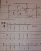
Hi all.I made a simple circuit (see pic) to try and clear up my confusion with opamps. Eg, does the + input get amplfied as well as the - one, and how? That sort of thing. I just wanted to see it all happening in practice.Unfortunately.... guess what, I'm as confused as ever.
It runs off +-9V. The 1K pots for the inputs have a 1.5K res on each end so I can get about -2V to 2V from each. The gain should, I believe, be 2.
The second table contains what I thought the output should be if the gain was 1, ie the - input inverted and added to the + input value.The third table shows the same thing, but with a gain of two, ie everything doubled.
In the first table is what I actually got, ignoring some decimal places in the measurements. Not very similar to table two...
Can anyone please explain??Thank-you very much again!Graham.


