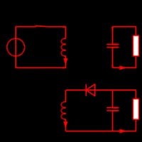
I have designed an inverting Buck-Boost converter whose output is floating. I would like the microcontroller to change the duty cycle of the converter to keep a steady voltage regardless of the impedance of the load. I want a maximum voltage of about 60v and absolutely not lower than 50v. The negative rail dips to about -32v when the power supply is pushed to this point.
Essentially, I cannot reference the outputs to the ground of my microcontroller without, at best, getting nonsense results, or at worst, destroying the IC.
My thought was to use a differential amplifier to sense the output of the converter and give a signal to the microcontroller. This has not worked as planned, for a few reasons. Primarily, the negative output goes below my ground voltage, and every op-amp I have been able to find does not allow a voltage lower than -0.3v below the negative rail. I need to be able to sense the difference in voltage between the positive and negative outputs regardless of whether one of the outputs goes below "ground" as seen by the op-amp. I do not want to have to give my op-amp a negative rail voltage of -32v unless this is the only way.
My circuit is essentially the same as the prototypical buck-boost converter (attached), except I have chosen to low-side switch for efficiency purposes.


