logo elektroda
logo elektroda
X
logo elektroda

What was the Tuya Wi-Fi module doing inside the computer? Updating the PC Power Switch Remote firmwa

p.kaczmarek2 1224 13

TL;DR

  • A Tuya Wi‑Fi PCIe card remotely controls a desktop PC’s power and reset buttons, bypassing the case switches with optocoupler-isolated inputs and outputs.
  • The board moved from a CBU BK7231N module to BK7238, and it can be flashed with OpenBK using a USB-to-UART converter and BK7231GUIFlashTool.
  • It costs just over $10, comes in Wi‑Fi and Zigbee versions, and the seller warns that branded computers may need specific BIOS settings.
  • Custom OBK scripts can map short and long presses to relay closures, add Home Assistant buttons, and enforce a child-lock condition that blocks power-on from the case.
  • The final result is a cloud-free remote PC power/reset switch that can boot, reset, and lock a computer, though Wake-on-LAN may already cover some use cases.
AI summary based on the discussion. May contain errors.
ADVERTISEMENT
This content has been translated flag-pl » flag-en View the original version here
📢 Listen (AI voice):
  • What was the Tuya Wi-Fi module doing inside the computer? Updating the PC Power Switch Remote firmwa
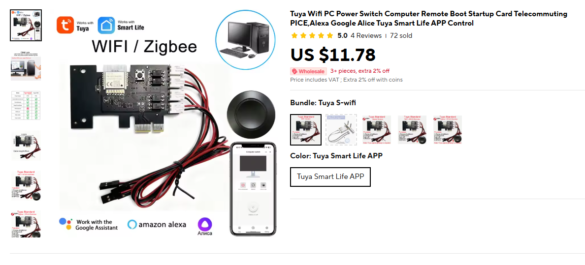
    The PCIe card shown here allows remote control of two buttons on a desktop computer – power and reset. It is available in two versions, Wi-Fi and Zigbee; here we will be looking at the former. The original buttons are completely bypassed, and the module offers two inputs and outputs isolated by optocouplers. This means it can provide a child lock function – preventing the computer from being switched on from the case. All of this is also available in the RF version, but we’ve opted for the Wi-Fi-only version – for just over $10:
    What was the Tuya Wi-Fi module doing inside the computer? Updating the PC Power Switch Remote firmwa
    The seller warns that the device does not work on branded computers and requires appropriate BIOS settings.

    What was the Tuya Wi-Fi module doing inside the computer? Updating the PC Power Switch Remote firmwa
    The whole thing is also available in a PRO version with an additional radio remote control:
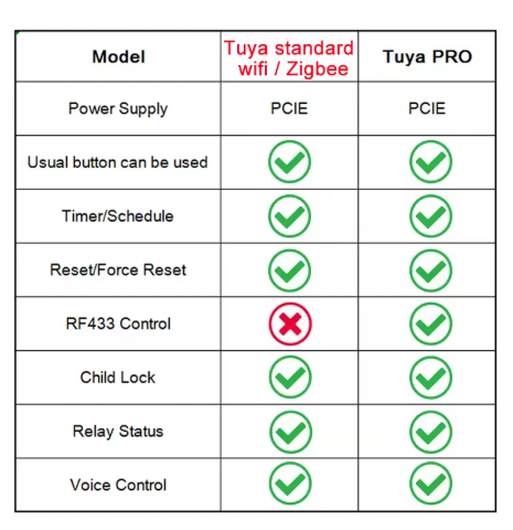
    What was the Tuya Wi-Fi module doing inside the computer? Updating the PC Power Switch Remote firmwa
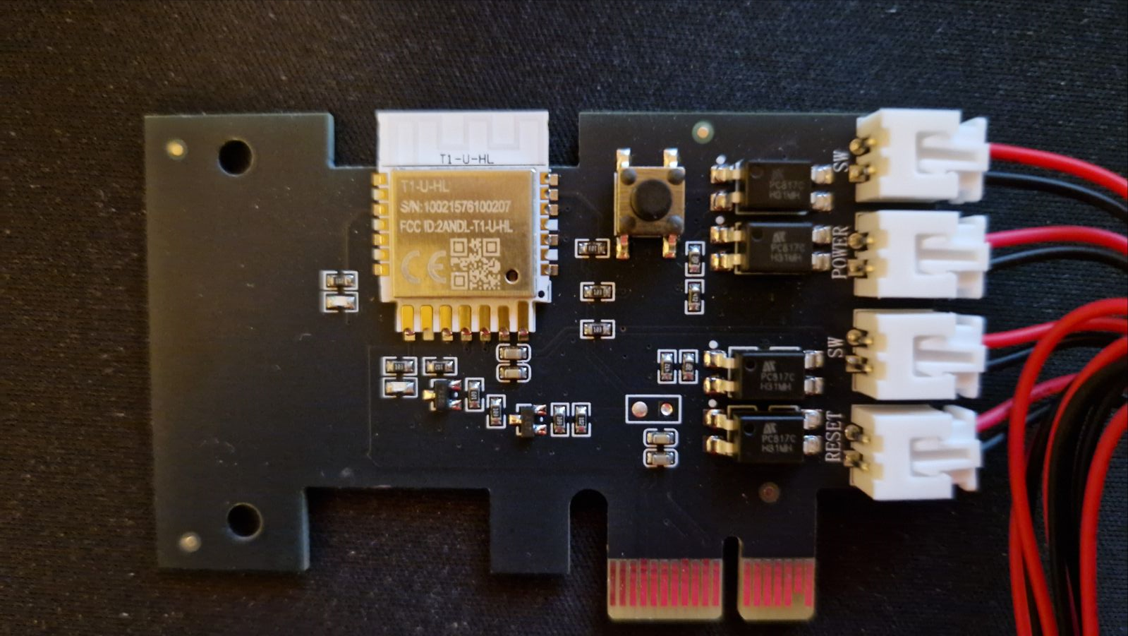
    Here’s a close-up of the board – there are four pairs of wires, two pairs are inputs and two are outputs. The device, with its factory settings, automatically pairs them; short-circuiting one input (where the button will be) causes a short-circuit in the output (where we’ll connect the motherboard):
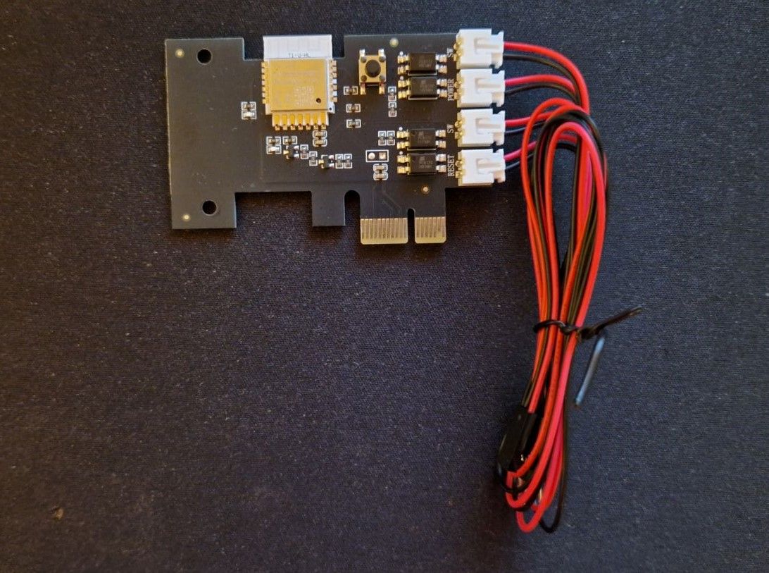
    What was the Tuya Wi-Fi module doing inside the computer? Updating the PC Power Switch Remote firmwa What was the Tuya Wi-Fi module doing inside the computer? Updating the PC Power Switch Remote firmwa
    The whole thing used to be on a CBU module (BK7231N), but it’s now on the BK7238:
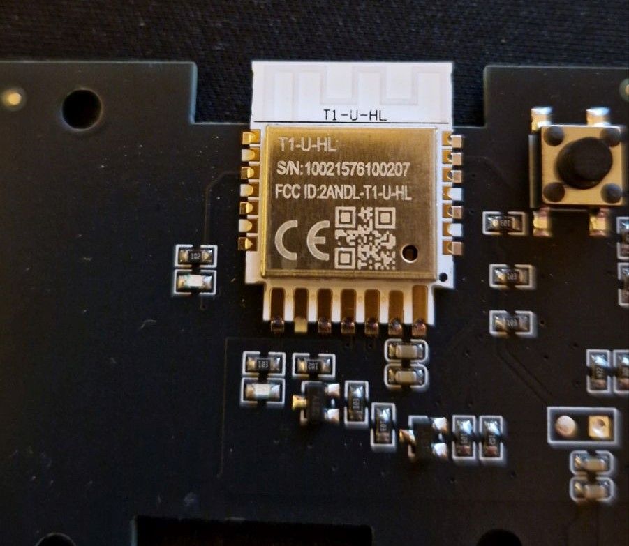
    What was the Tuya Wi-Fi module doing inside the computer? Updating the PC Power Switch Remote firmwa
    A few words about the app are also in order. Tuya comes pre-installed, allowing you to control it for free from anywhere in the world. It also features a timer and integration with Google, Alexa and similar voice assistants.

    Firmware update
    However, we wanted to experiment a bit more and flash our own firmware onto it. This is where you need to think carefully, because if you don’t have a server on the internet, there may be a problem with controlling it from behind your router, but this is normal for solutions such as Tasmota or ESPHome. Here, we’ll upload our multi-platform IoT firmware supporting as many as 32 platforms to the module.
    We’ve already shown the T1-U-HL pinouts on the forum: Data sheet for the T1, T1-M and T1-3S Tuya BK7238 modules, pinouts and flashing, Home Assistant
    You can change its firmware – all you need is a USB-to-UART converter:
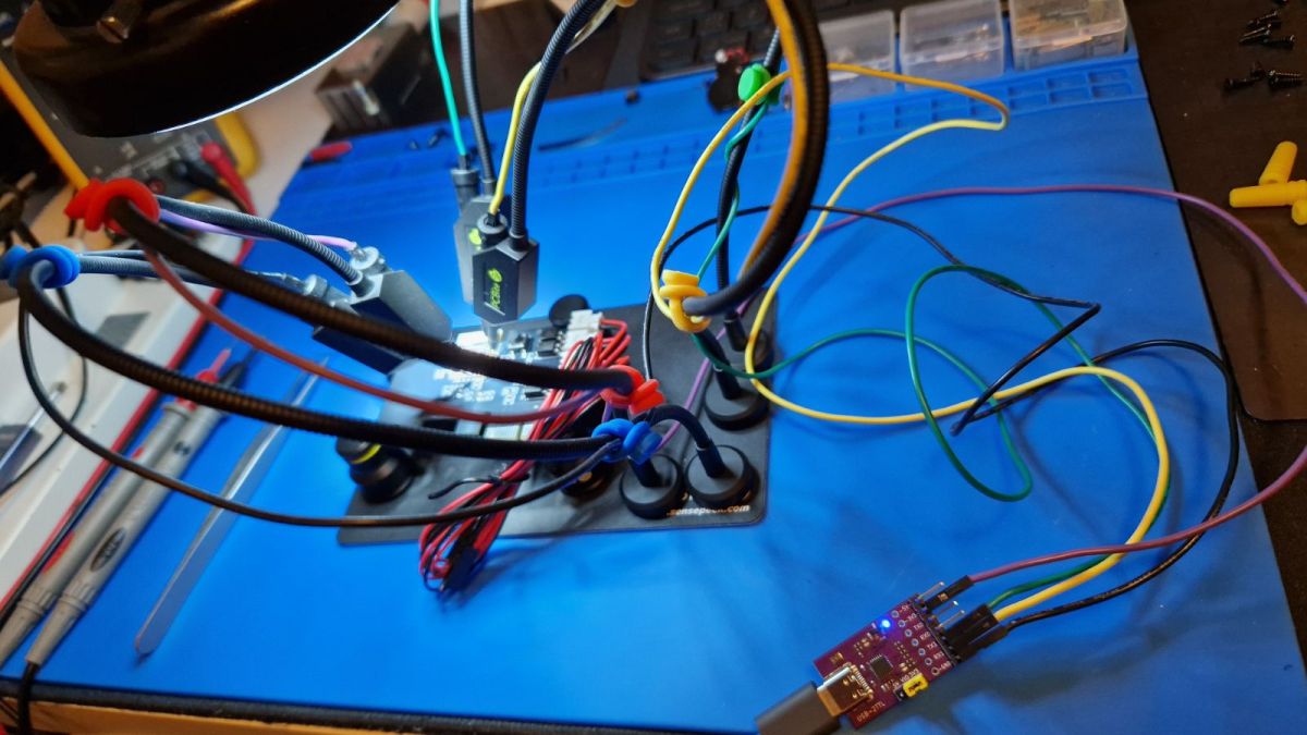
    What was the Tuya Wi-Fi module doing inside the computer? Updating the PC Power Switch Remote firmwa
    First, we burn the firmware using our Flasher, then we upload the OBK:
    https://github.com/openshwprojects/BK7231GUIFlashTool
    Copy of the firmware:
    https://github.com/openshwprojects/FlashDumps/commit/f731ea9b6c9477ab72163f2231dbda793ee3239b
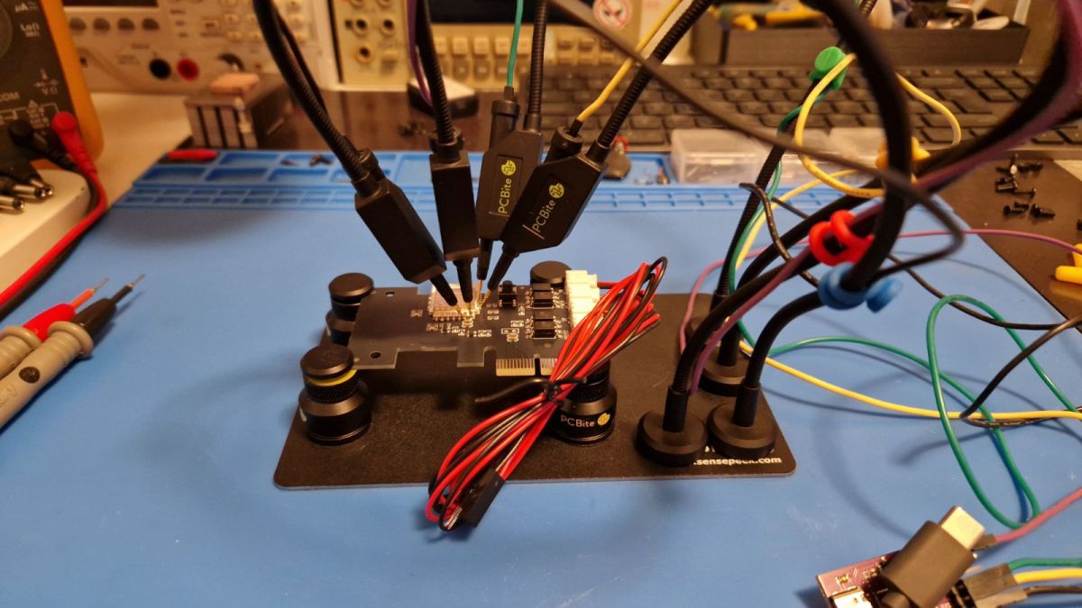
    However, the Flasher did not detect the GPIO this time:
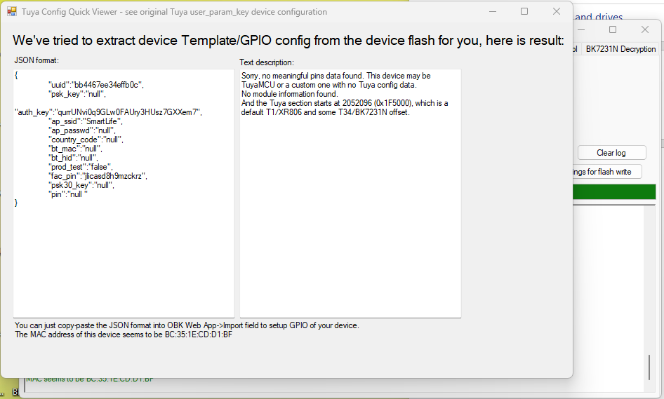
    What was the Tuya Wi-Fi module doing inside the computer? Updating the PC Power Switch Remote firmwa
    We determined the GPIO roles by tracing the paths:
    Code: JSON
    Log in, to see the code

    There are two ways to script the device.
    1. in Home Assistant using their automations
    2. on the Beken board itself, via autoexec.bat
    Autoexec.bat allows the OBK to handle device events and add buttons to the main panel:
    
    
    alias force_power_off backlog setChannel 1 1; addRepeatingEvent 5 1 setChannel 1 0
    alias short_click backlog setChannel 1 1; addRepeatingEvent 1 1 setChannel 1 0
    
    startDriver httpButtons
    
    setButtonEnabled 0 1
    setButtonLabel 0 "Toggle Power"
    setButtonCommand 0 short_click 
    
    [inContentAd]
    
    setButtonEnabled 1 1
    setButtonLabel 1 "Force POWER off"
    setButtonCommand 1 force_power_off 
    
    SetChannelLabel 1 PWR
    SetChannelLabel 2 RESET
    SetChannelLabel 3 PWR_ON
    
    addEventHandler OnHold 21 force_power_off 
    addEventHandler OnClick 21 short_click
    

    The script above:
    - sets the channel names
    - adds events that manually map a button click and a long press to a short and long relay closure respectively
    - adds buttons to the UI that trigger these events – these will then also be visible in Home Assistant
    Screenshot of a panel with a single scripted button:
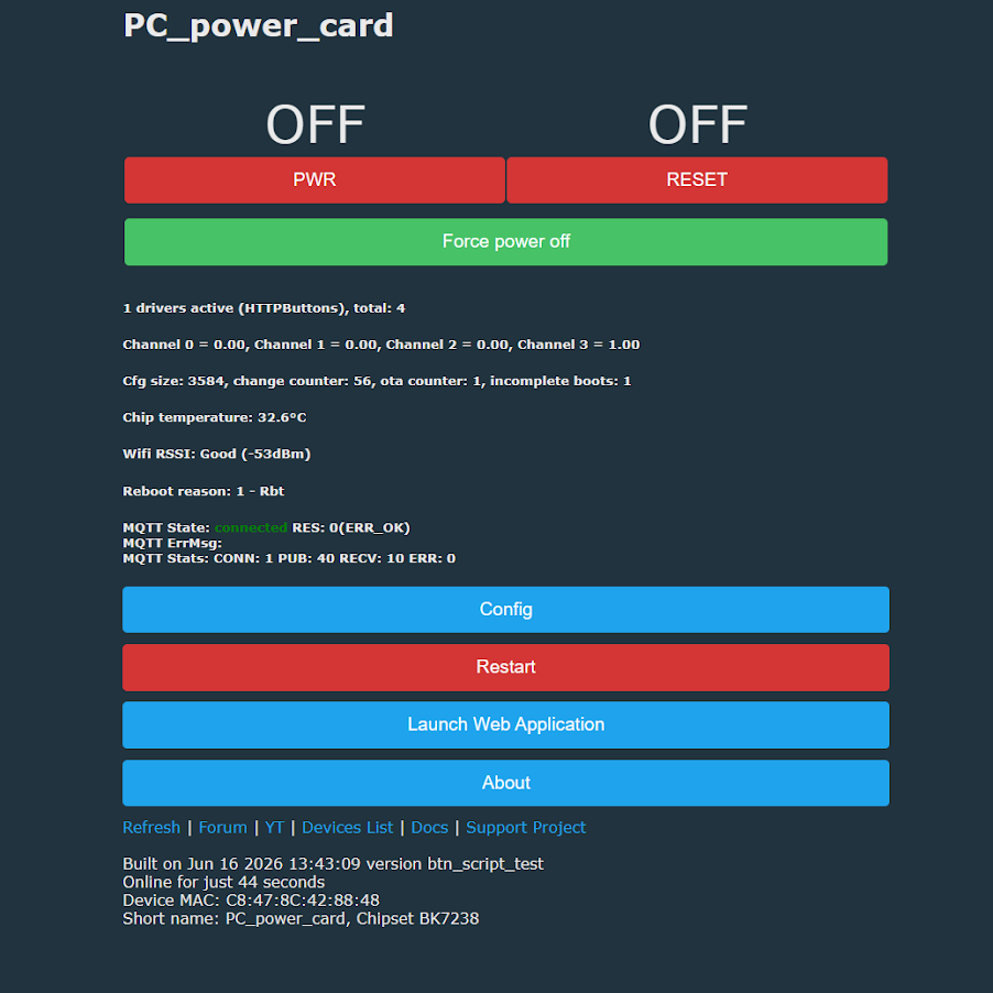
    What was the Tuya Wi-Fi module doing inside the computer? Updating the PC Power Switch Remote firmwa
    Similarly, you can add a RESET button (a second button and relay):
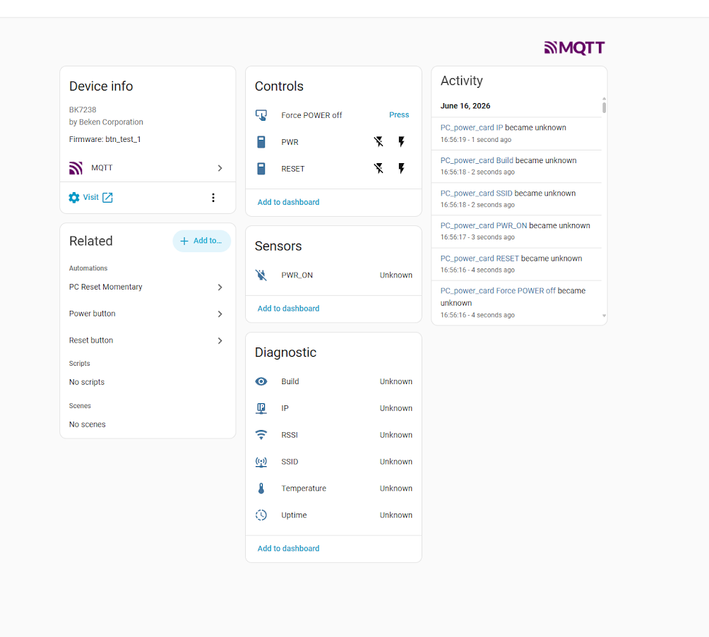
    Home Assistant dashboard showing PWR and RESET controls and an MQTT activity log
    This way, you can bring this module to life without the cloud. There is still the matter of the child lock – the remote lock. This can be added by including an additional condition check in the button and event handling via if :
    
    SetChannelLabel 10 "Child Lock"
    
    addEventHandler OnHold 21 if $CH10==1 then force_power_off 
    

    Then, click events will only be triggered when we allow them to.

    Of course, this is not the only way to configure it. One could, for example, try to hard-code the connection between the buttons and the relays by assigning the inputs the dInput role (digital input) and the same channels as the relays, but then we would lose remote control. The digital value from the inputs would be copied to the outputs. For this reason, scripting seems to be the sensible solution here.

    For more information, please visit the project repository , the page with documentation and the examples of OBK scripts .

    To sum up , the module seems quite useful. It works well both in its factory-set state, where you immediately gain remote access via the Tuya app, and after a firmware update, when using Home Assistant or a similar system connected to the internet.
    The usefulness of this solution is somewhat diminished by the fact that many computers can be booted remotely via Wake-on-LAN. However, this is not always convenient to set up from outside the local network, and some hardware configurations do not support it at all. For this reason, such a module can still prove very practical as a simple way to boot a computer remotely, particularly when combined with a remote desktop configured to be accessible immediately after the system starts up.
    In addition, there is the option to remotely reset the computer and use the ‘child lock’ function, which locks the physical buttons on the case.
    Can you think of any interesting uses for such a remote PC switch?

    Cool? Ranking DIY
    Helpful post? Buy me a coffee.

    About Author
    p.kaczmarek2
    Moderator Smart Home
    Offline 
    p.kaczmarek2 wrote 14713 posts with rating 12789, helped 659 times. Been with us since 2014 year.
  • ADVERTISEMENT
  • #2 21926449
    mkpl
    Level 37  
    Posts: 5674
    Help: 306
    Rate: 858
    I’m a bit disappointed. At first glance, I thought the computer was controlled via a bus (which would have been interesting). Unfortunately, it’s controlled via cables and the PCIe is just for power. In this version, it’s a waste of a slot.
  • ADVERTISEMENT
  • #3 21926474
    j4rek
    Level 19  
    Posts: 370
    Help: 8
    Rate: 103
    A standby voltage is required (available on the PCIe 3.3V aux connector). Alternatively, you would need to tap into the power supply’s wiring (the 5V standby line, pin 9, purple wire) and convert the 5V to 3.3V.
  • #4 21926475
    p.kaczmarek2
    Moderator Smart Home
    Posts: 14713
    Help: 659
    Rate: 12789
    That’s an interesting idea about controlling it via PCIe – the question is, just how practical is it? Does anyone know whether controlling it via PCIe would make sense, whether it would offer any added benefits, and whether it would even be possible? Perhaps I could consider a DIY version.
    Helpful post? Buy me a coffee.
  • Tuya remote power switch module with reset support

    #5 21926620
    Stanley_P
    Level 28  
    Posts: 1310
    Help: 62
    Rate: 291
    Hello. Half-jokingly, half-seriously, this topic reminded me of something like this. It doesn’t require any intervention on the computer, although you’ll need two of them for power and reset. And it won’t block access to the physical buttons ;-)
    https://pl.aliexpress.com/item/1005008046208343.html
    (example link)
  • Check whether the PC starts without the button cables

    #6 21926635
    CMS
    VIP Meritorious for electroda.pl
    Posts: 8466
    Help: 258
    Rate: 2600
    p.kaczmarek2 wrote:
    The original buttons are completely bypassed,


    I have this module and both the app controls and the buttons work. The buttons are connected to the motherboard via the supplied cables
    with a splitter, in parallel with the module.
    Are you sure that if you connect the module only to the PCI-E slot and leave the cables hanging loose, the computer won’t start up? Because I seem to recall that when I bought it a few years ago, due to an incorrect label on the cables, I had some trouble connecting it, and it’s possible – if I’m not mistaken – that on the first attempt I booted the computer without those cables. Check this out to make sure it’s not the problem.
  • PCIe 3.3v rail used for power and status

    #7 21926847
    DeDaMrAz
    Level 23  
    Posts: 620
    Help: 34
    Rate: 130
    @CMS

    I did run multiple checks on the device and no with OBK FW inside it is not possible to turn the PC on by accident, with careful scripting bunch of features can be added as @p.kaczmarek2 mentioned Child lock for example or force shutdown, even disabling the buttons on the PC case.

    Device does use the PCI-E for power and for "Powered ON" signal as it taps to 3v3 rail on the PCI-E slot for that. I would call it a useful little gadget for the price.
  • #8 21927195
    CMS
    VIP Meritorious for electroda.pl
    Posts: 8466
    Help: 258
    Rate: 2600
    DeDaMrAz wrote:
    I’ve carried out a series of tests on this device and no, with the OBK FW software, there’s no possibility of the computer switching on accidentally


    I didn’t mention anything about it switching on accidentally.
  • ADVERTISEMENT
  • #9 21927196
    p.kaczmarek2
    Moderator Smart Home
    Posts: 14713
    Help: 659
    Rate: 12789
    It’s a question of translation from English into Polish, but generally speaking, this module cannot power on the computer without being connected to the button pins on the motherboard. Although I’m still curious – if there are modules that can do this, how do they work?
    Helpful post? Buy me a coffee.
  • #11 21927440
    krzbor
    Level 29  
    Posts: 1780
    Help: 42
    Rate: 1069
    Computer cases are made of metal. How does the signal cope?
  • ESPHome-flashed module with power-sense GPIO added

    #12 21927954
    Hetii
    Level 17  
    Posts: 519
    Help: 4
    Rate: 420
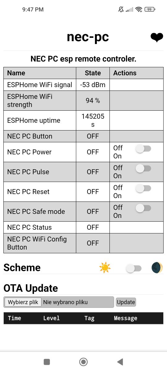
    I’ve modified a module like this https://devices.esphome.io/devices/sinilink-xy-wpce by flashing it with esphome.
    I also soldered a wire from the power connector to a free GPIO pin to confirm that the PC is switched on.
    Despite the thick sheet metal and the almost airtight casing, my ESP has no trouble connecting to the router.
    This is what it looks like at my place:
    Phone screenshot of “nec-pc” ESPHome panel with status table and PC control toggles
  • ADVERTISEMENT
  • #13 21935121
    krzbor
    Level 29  
    Posts: 1780
    Help: 42
    Rate: 1069
    I bought one of these on ZigBee. After connecting and pairing it, the Z2M recognised it as a TS011F plug. The plug’s switch works. Each time it’s switched, it simulates a press of the Power button. Unfortunately, I don’t have a Reset button or a long Power button. Has anyone used this with the Z2M?
  • Z2M external converter for PCIe power/reset card

    #14 21936214
    krzbor
    Level 29  
    Posts: 1780
    Help: 42
    Rate: 1069
    Z2M allows you to create a new device definition. After some tweaking and with Claude’s help, I managed to define the device description for Z2M:
    Code: Javascript
    Log in, to see the code

    The definition had to be in fingerprint format, otherwise it would overwrite my original TS011F plug-in :) If anyone connects this device, they should check the manufacturer carefully. Mine is very strange: _TZ32981000000_rghq9fag. If it’s different, but the layout looks similar, you can change it to your own.
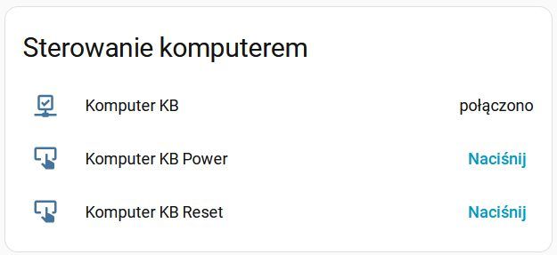
    It’s very easy to add your own device definition to Z2M. In the folder containing the Z2M configuration (the configuration.yaml file), create a directory called external_converters. Place the converter files in this directory. All you need to do is save the contents of the JavaScript code above as, for example, pcie.js and copy it into that directory. After restarting Z2M, the new definition will be visible. You can add it to the dashboard:
    “Computer control” panel with three entries: Computer KB, Power, Reset, and “Press” action links.
    There are two buttons: power and reset. I’ve also added a “PING” integration, which allows me to see whether the computer is running or not (whether it can be pinged).
📢 Listen (AI voice):
ADVERTISEMENT