





Hello,
So i just bought this new LSC Smart connect Floor Lamp at a local Action store and wanted to try and flash OpenBeken to it. Below some pictures of the device.
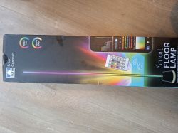
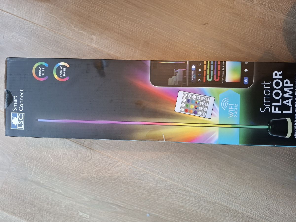
Front of the box:
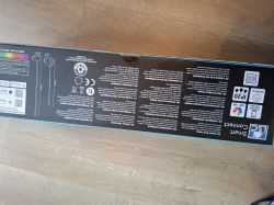
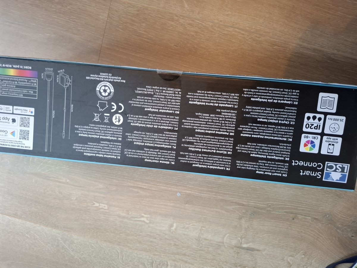
Back of the box:
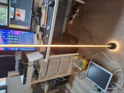
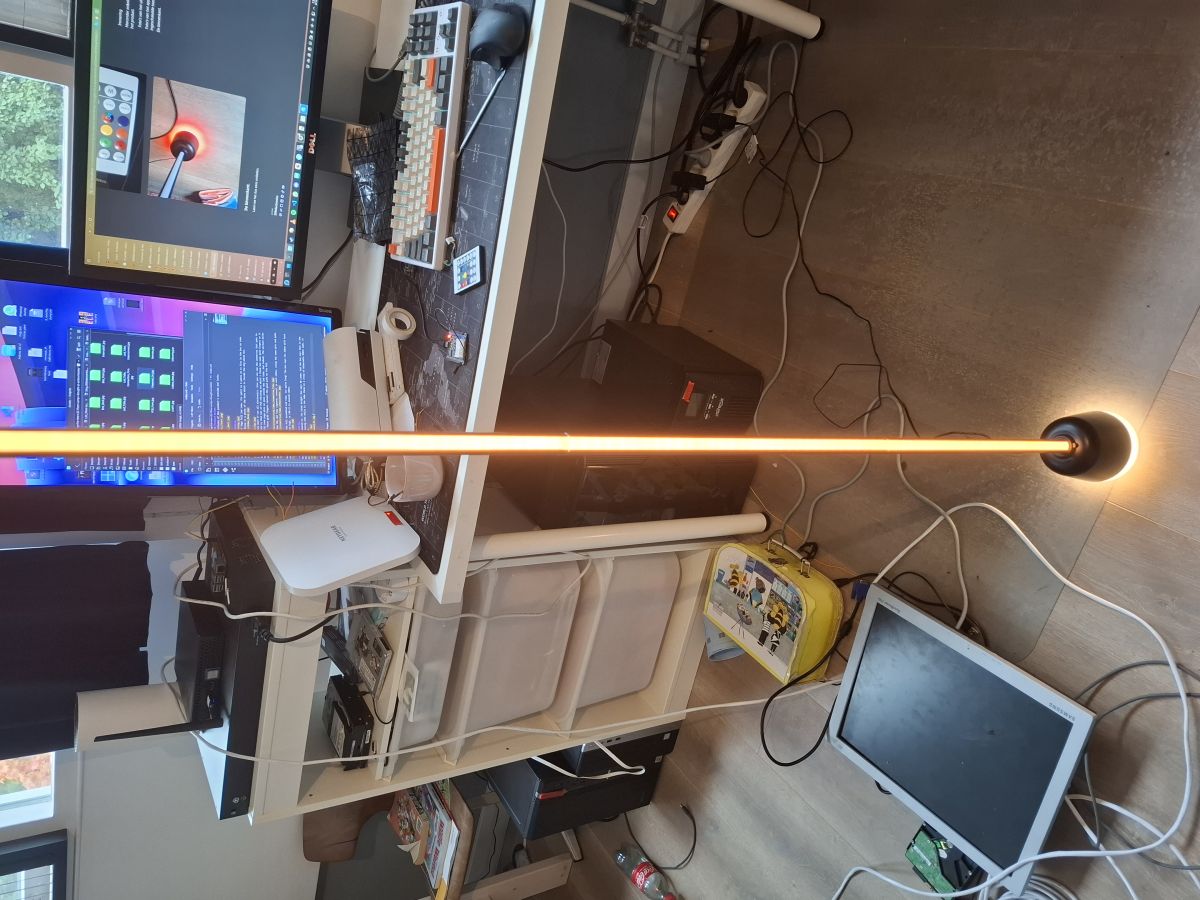
Fully assembled and working:
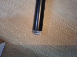
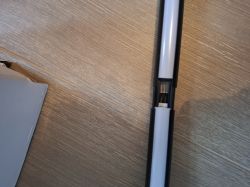
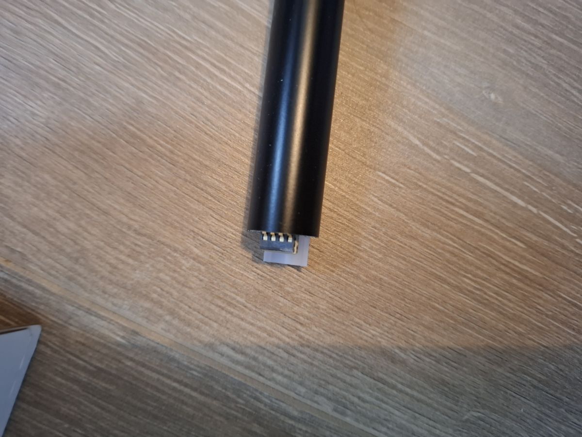
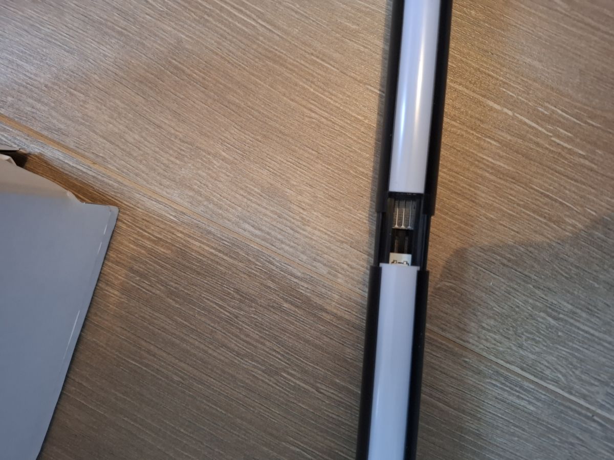
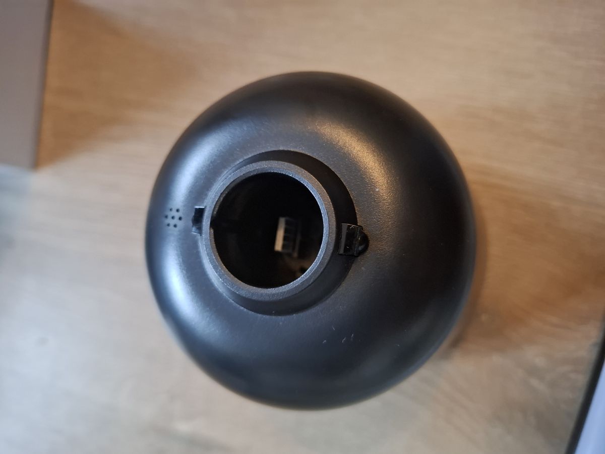
Its actually a hybrid lamp making use of regular dumb analog LED's in the base and Addressable digital LED's in the led tube going up to the sky (Obviously, not fully, but you get the idea). Below is a picture of the pins inside the led tube as that's how it connects to the base and the other led tubes. Yes it does require you to assemble it as obviously otherwise it would not have fitted in the box. It is very easy to do and pretty much plug and play.
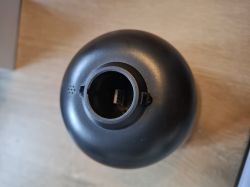
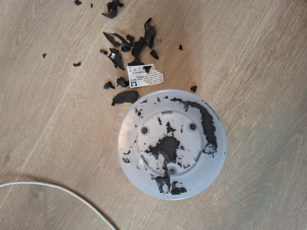
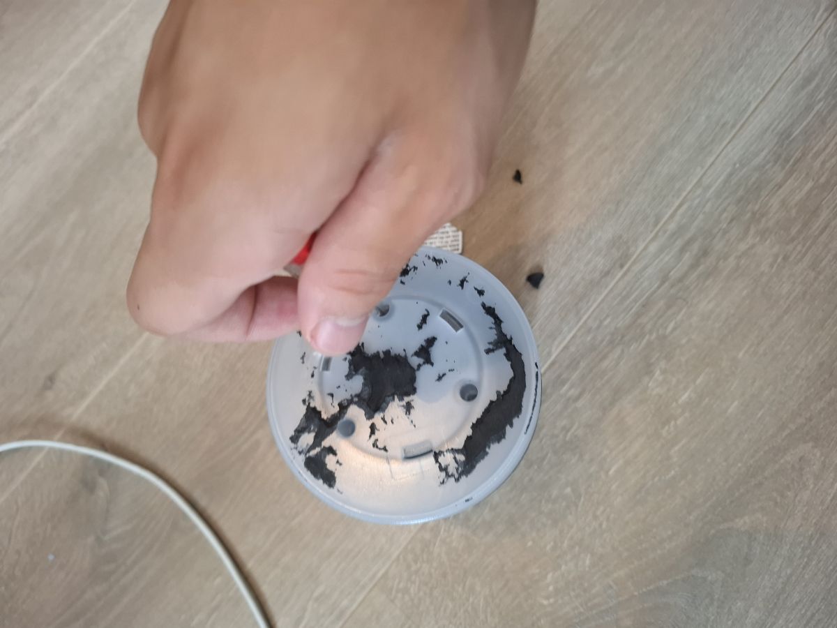
So lets open it up. Welp, i managed to ruin the bottom foam but oh well, at least now we see the screws. I would recommend people to remove it using glue remover or heat to soften the glue and not repeat my mistake.
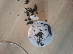

After unscrewing you can see the internals. And also in the bottom part, there is a heavy weight to make it not tip over easily. And the led strip can be unplugged by the little connector.
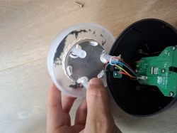
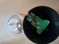
The power jack is on a separate PCB and is sadly soldered so you cant unplug it. But you can unscrew it
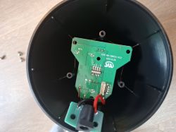
Then undo the visible screws and you can take the PCB out. I also had to de solder the Microphone wires as that was whats keeping in the PCB. Below a picture of the board.
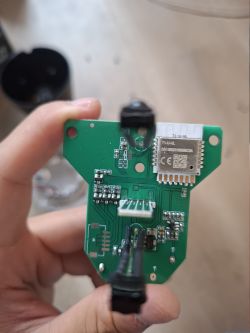
On it is the newer Tuya T1-U-HL module incorporating a Beken bk7238 chip. This chip seems to be a more modern and efficient variant of the bk7231 i read. Also it is supported by OpenBeken so that's nice!
Also see those 2 sets of Rx and TX pads? Those are 2 individual UART's. I think UART1 is for programming and UART2 for firmware debug. Anyways i soldered to UART1 and could now use openbekenflasher.
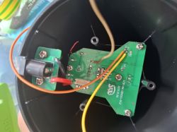
First i went ahead and dumped the firmware so i have a backup and possibly could pull out the Tuya configuration. Sadly it could not extract the Tuya configuration so i had to resort to reverse engineering and trial and error on the GPIO's. I did in the meantime flash OpenBeken and configured it. Then i started flipping GPIO's randomly (I know, probably not the best idea but i quickly got the red, green and blue and cw/ww GPIO (cw/ww are both hooked up to 1 gpio) for the base led strip. So the base could light up already!
So i found out that RED of the base strip gone to P8, GREEN of the base strip gone to P24, BLUE of base strip gone to P9 and the WHITE colors gone to P26. So i set those to there respected channels (1, 2, 3, 5). And now i could control the warm/cold white and all RGB colors.
Then i traced back the GPIO's for the IR sensor and the Data input for the addressable LED's IR was P23 and Data Input of the addressable strip was hooked up to P16 like typical with ws2812/SM16703 compatible strips. After enabling the SM16703 driver and configuring it to drive 96 Addressable LED's (32x LED's per led tube segment, thus 3x tube segments) and then starting the Pixelanim driver i got life! But the RED and GREEN where reversed. No worries i just had to set the driver to output in GRB mode and that fixed it.
So i spent some hours on it and playing around a bit and half of it is working. The Addressable strip is working as expected and can be controlled from home assistant or the OpenBeken WebUI. The base sadly cant be controlled from those 2, but you can control it via MQTT commands. I believe this is a limitation in OpenBeken itself cause i doubt its common for products to have 1 wifi module doing multiple functions/driving multiple components. Or atleast i have not yet been able to get individual controls for both or to get it to control both separate reliably. But yeah in short, the lights work. The remote does not work yet, but that requires capturing the commands and then defining an action for each command using event listeners and stuff i am currently too busy for work, so i cant really do that at the moment but happy for anyone who might be able to use this as a launchpad into getting It properly working. Also i have not yet gotten the microphone to work but i dont need it anyways and i kinda broke the pads on the PCB while soldering it back so that stays for now non-working.
Below the working template.
GPIO's:
RED (base): P8
GREEN (base): P24
BLUE (base): P9
Warm/Cold white: P5
IR Receiver: P23
Addressable leds: P16
This is my first time posting on elektroda and if i need to edit/modify something, please let me know peacefully. Thanks in advance! I will try to provide the best/most information i managed to gather. Also happy for any feedback/help/suggestions and feel free to leave a comment or contact me. I also hope this inspires others to try and improve my current template or hack more of the newer LSC/Tuya gear as i believe Action also has a Little smart table lamp.
Have a good day/night and i will cut it off here. Also i dont know if i posted in the right forum, but if i posted it wrong. Please also let me know!
So i just bought this new LSC Smart connect Floor Lamp at a local Action store and wanted to try and flash OpenBeken to it. Below some pictures of the device.
Front of the box:
Back of the box:
Fully assembled and working:
Its actually a hybrid lamp making use of regular dumb analog LED's in the base and Addressable digital LED's in the led tube going up to the sky (Obviously, not fully, but you get the idea). Below is a picture of the pins inside the led tube as that's how it connects to the base and the other led tubes. Yes it does require you to assemble it as obviously otherwise it would not have fitted in the box. It is very easy to do and pretty much plug and play.
So lets open it up. Welp, i managed to ruin the bottom foam but oh well, at least now we see the screws. I would recommend people to remove it using glue remover or heat to soften the glue and not repeat my mistake.
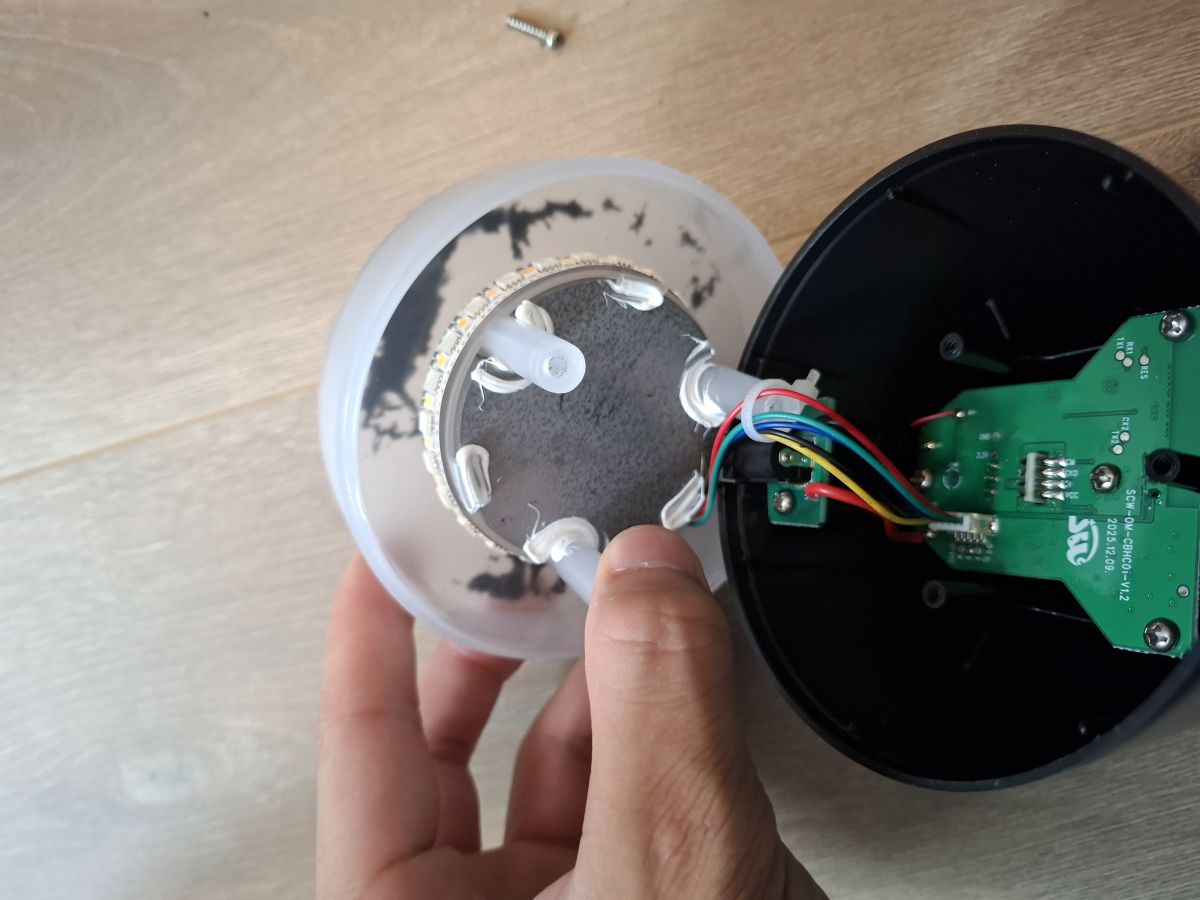
After unscrewing you can see the internals. And also in the bottom part, there is a heavy weight to make it not tip over easily. And the led strip can be unplugged by the little connector.
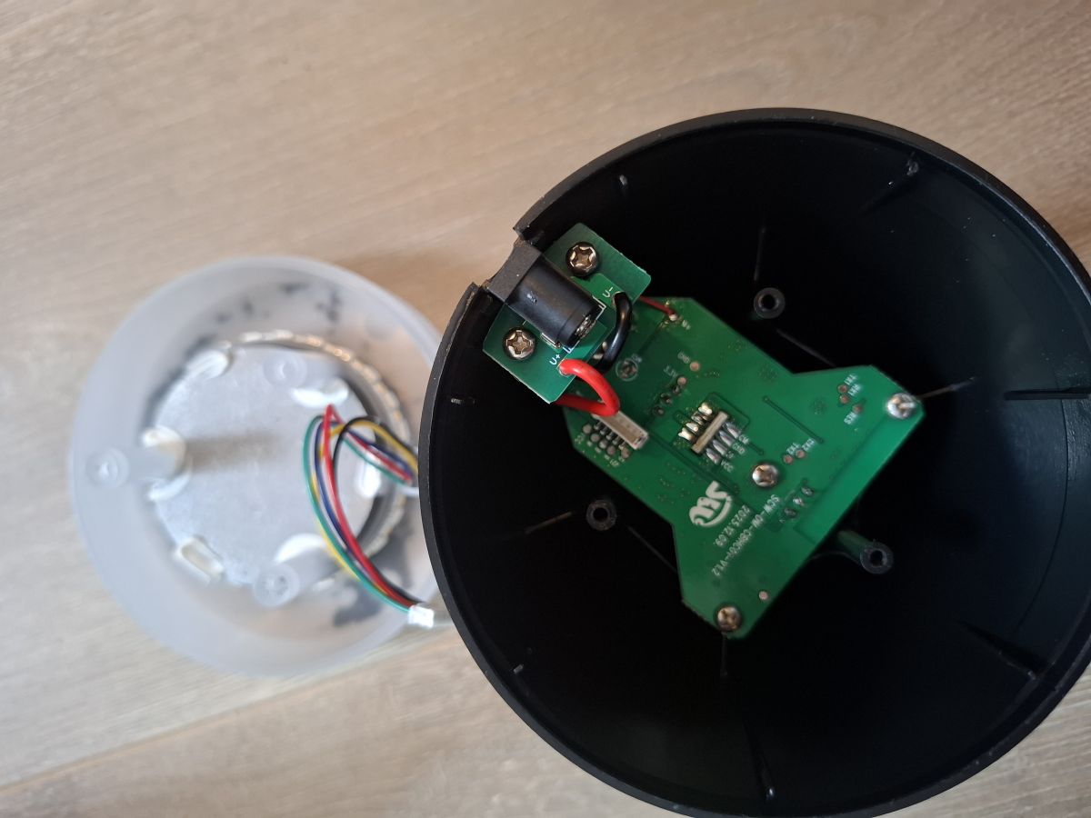
The power jack is on a separate PCB and is sadly soldered so you cant unplug it. But you can unscrew it
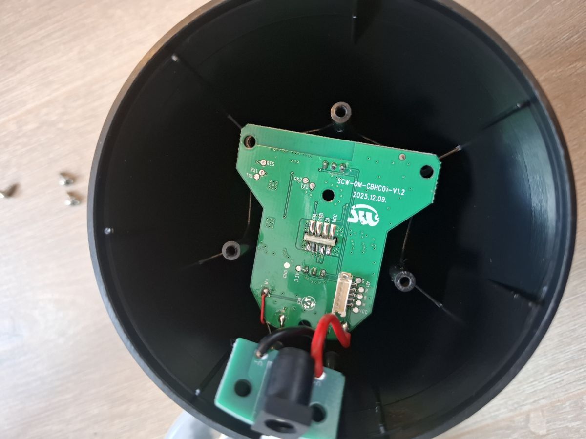
Then undo the visible screws and you can take the PCB out. I also had to de solder the Microphone wires as that was whats keeping in the PCB. Below a picture of the board.
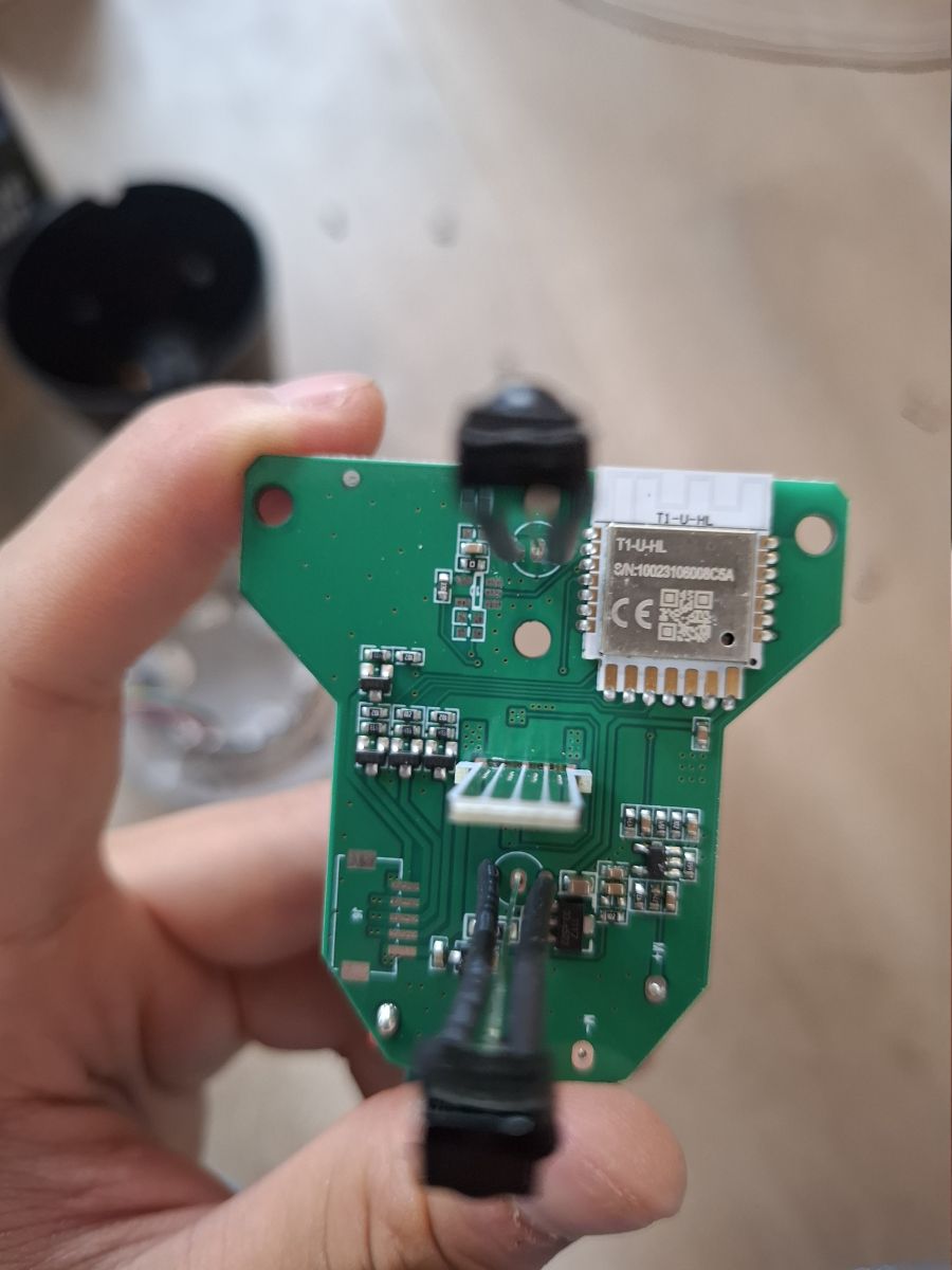
On it is the newer Tuya T1-U-HL module incorporating a Beken bk7238 chip. This chip seems to be a more modern and efficient variant of the bk7231 i read. Also it is supported by OpenBeken so that's nice!
Also see those 2 sets of Rx and TX pads? Those are 2 individual UART's. I think UART1 is for programming and UART2 for firmware debug. Anyways i soldered to UART1 and could now use openbekenflasher.
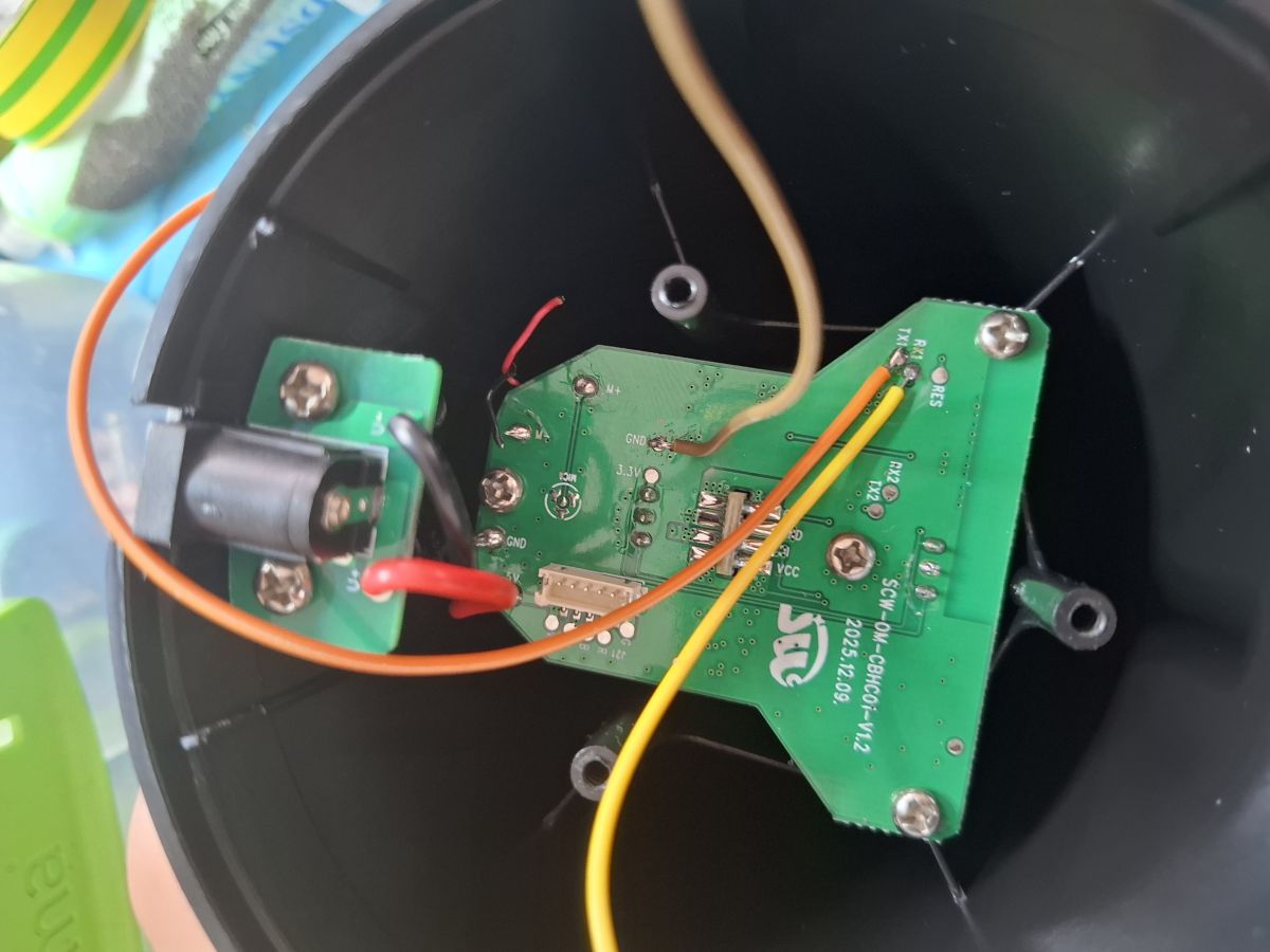
First i went ahead and dumped the firmware so i have a backup and possibly could pull out the Tuya configuration. Sadly it could not extract the Tuya configuration so i had to resort to reverse engineering and trial and error on the GPIO's. I did in the meantime flash OpenBeken and configured it. Then i started flipping GPIO's randomly (I know, probably not the best idea but i quickly got the red, green and blue and cw/ww GPIO (cw/ww are both hooked up to 1 gpio) for the base led strip. So the base could light up already!
So i found out that RED of the base strip gone to P8, GREEN of the base strip gone to P24, BLUE of base strip gone to P9 and the WHITE colors gone to P26. So i set those to there respected channels (1, 2, 3, 5). And now i could control the warm/cold white and all RGB colors.
Then i traced back the GPIO's for the IR sensor and the Data input for the addressable LED's IR was P23 and Data Input of the addressable strip was hooked up to P16 like typical with ws2812/SM16703 compatible strips. After enabling the SM16703 driver and configuring it to drive 96 Addressable LED's (32x LED's per led tube segment, thus 3x tube segments) and then starting the Pixelanim driver i got life! But the RED and GREEN where reversed. No worries i just had to set the driver to output in GRB mode and that fixed it.
So i spent some hours on it and playing around a bit and half of it is working. The Addressable strip is working as expected and can be controlled from home assistant or the OpenBeken WebUI. The base sadly cant be controlled from those 2, but you can control it via MQTT commands. I believe this is a limitation in OpenBeken itself cause i doubt its common for products to have 1 wifi module doing multiple functions/driving multiple components. Or atleast i have not yet been able to get individual controls for both or to get it to control both separate reliably. But yeah in short, the lights work. The remote does not work yet, but that requires capturing the commands and then defining an action for each command using event listeners and stuff i am currently too busy for work, so i cant really do that at the moment but happy for anyone who might be able to use this as a launchpad into getting It properly working. Also i have not yet gotten the microphone to work but i dont need it anyways and i kinda broke the pads on the PCB while soldering it back so that stays for now non-working.
Below the working template.
Code: JSON
GPIO's:
RED (base): P8
GREEN (base): P24
BLUE (base): P9
Warm/Cold white: P5
IR Receiver: P23
Addressable leds: P16
This is my first time posting on elektroda and if i need to edit/modify something, please let me know peacefully. Thanks in advance! I will try to provide the best/most information i managed to gather. Also happy for any feedback/help/suggestions and feel free to leave a comment or contact me. I also hope this inspires others to try and improve my current template or hack more of the newer LSC/Tuya gear as i believe Action also has a Little smart table lamp.
Have a good day/night and i will cut it off here. Also i dont know if i posted in the right forum, but if i posted it wrong. Please also let me know!
