logo elektroda
logo elektroda
X
logo elektroda

We are modifying the relay controller so that it works without a microcontroller – ESP8266 Relay V2.

p.kaczmarek2 786 6

TL;DR LABEL_AI_GENERATED

  • The LC Technology ESP8266 Relay V2.3 is converted from a UART-controlled Wi-Fi bridge into a standalone, locally controlled Tasmota relay by removing its extra microcontroller.
  • Removing the UART jumpers enables ESP8266 flashing; the modification then routes an ESP GPIO through R5 to transistor Q1, which switches the relay coil.
  • The board runs from 12 V DC, while the relay-drive path uses R5, a 4.7 kΩ base resistor, and diode D3 to suppress coil switch-off spikes.
  • The modified relay responds from the Tasmota panel and its button, and Tasmota detects button-triggered state changes.
  • One of the two buttons may be lost because it was not connected to GPIO, and the reason for the original MCU remains unresolved.
AI summary based on the discussion. May contain errors.
ADVERTISEMENT
This content has been translated flag-pl » flag-en View the original version here
Listen:
  • We are modifying the relay controller so that it works without a microcontroller – ESP8266 Relay V2.
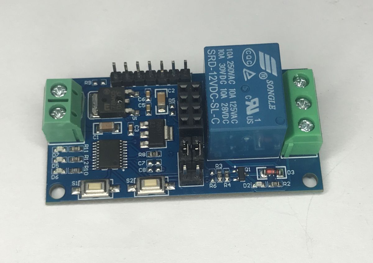
    I’d like to present a modification to the LC Technology ESP8266 Relay V2.3 controller, designed to work locally with the Tasmota firmware. This will be a rather unusual modification, as, for some inexplicable reason, the manufacturer decided to use an additional microcontroller to control the relay. Is the ESP8266 capable of driving the relay without an additional microcontroller? Let’s find out!

    The device discussed here was sent in by a reader; it is exactly the same unit as the one featured in the Tasmota thread:
    https://www.elektroda.pl/rtvforum/topic3760371.html#21922314
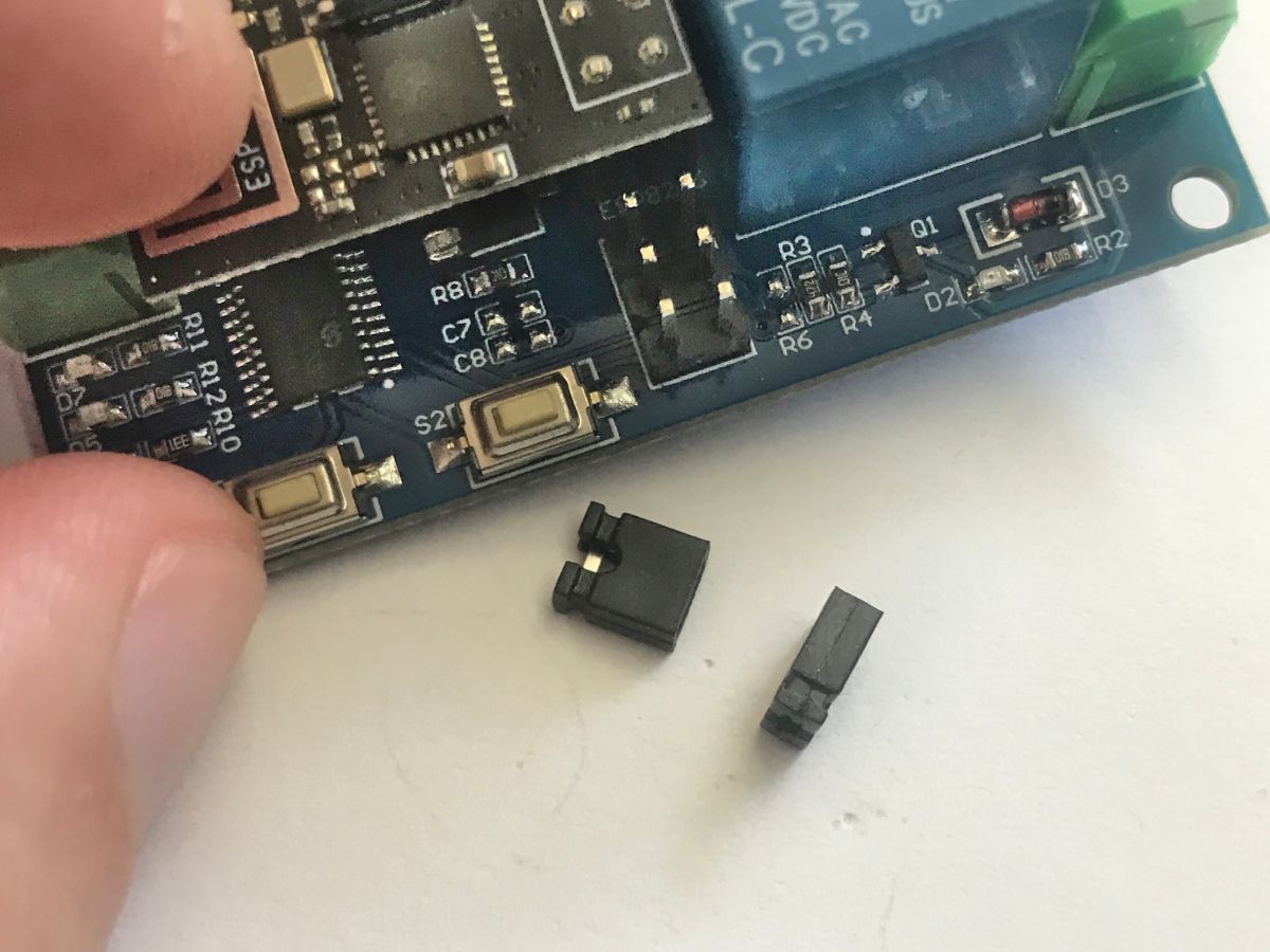
    The reader was having trouble updating the firmware. After connecting the UART, the ESP failed to respond to communication attempts. The device was sent to me so that I could investigate the situation. A mysterious pair of jumpers immediately caught my eye.
    We are modifying the relay controller so that it works without a microcontroller – ESP8266 Relay V2.
    Underneath the ESP8266 module is an additional microcontroller that communicates with the ESP via UART. But what for? Details of the protocol can be found on the Blakadder website; it seems fairly straightforward:
    https://templates.blakadder.com/LC-ESP8266.html
    But why make it so complicated? After all, Tasmota can control the ESP’s GPIO pins directly. For this reason, I decided on a different modification to Mr Blakadder’s, but more on that in a moment.
    First off – a copy of the original setup. Once the jumpers connecting the ESP’s UART lines to the MCU have been removed, esptool starts up correctly straight away.
    https://github.com/openshwprojects/FlashDumps/commit/ce13ed9575049e19c7a8c4a6f36283318770bfd4
    I briefly analysed the extracted firmware. Here is some of the information I found:
    - the firmware is 2 MB, but it is a 1:1 duplicate of a 1 MB image (MD5 sums match)
    - it contains the factory AT command firmware from Ai-Thinker / Espressif (Non-OS SDK 3.0 from 2020)
    - the default UART speed is 115,200 baud (bootloader v1.7 transmits at 74,880 baud)
    - the module sets up a SoftAP network named "AI-THINKER_XXXXXX" (IP 192.168.4.1) and supports SmartConfig (ESPTOUCH/AIRKISS)
    - By default, the ESP8266 acts solely as a Wi-Fi bridge to the UART, transmitting hex frames to the second MCU

    My idea was to remove the microcontroller and connect the ESP pins to a relay, a button and an LED, as described in the thread
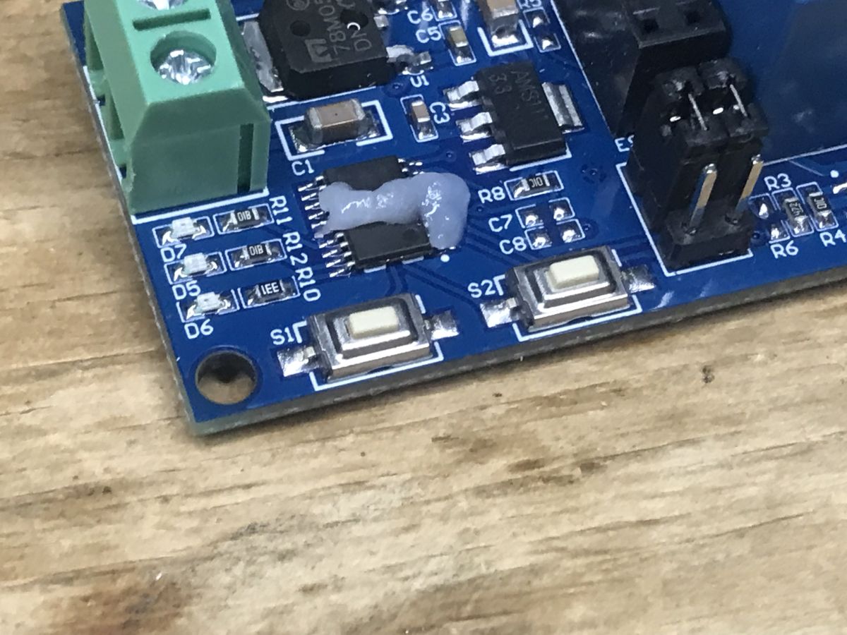
    ESP8266 and Tasmota – step-by-step Wi-Fi relay control . You can desolder the microcontroller using hot air, but it’s worth applying flux to the pins.
    We are modifying the relay controller so that it works without a microcontroller – ESP8266 Relay V2.
    I know my hot air gun well enough that I didn’t need to protect the screw terminals or nearby components with tape. With the right nozzle and sufficient power, the component comes off quickly, the board doesn’t swell and the other components don’t burn.
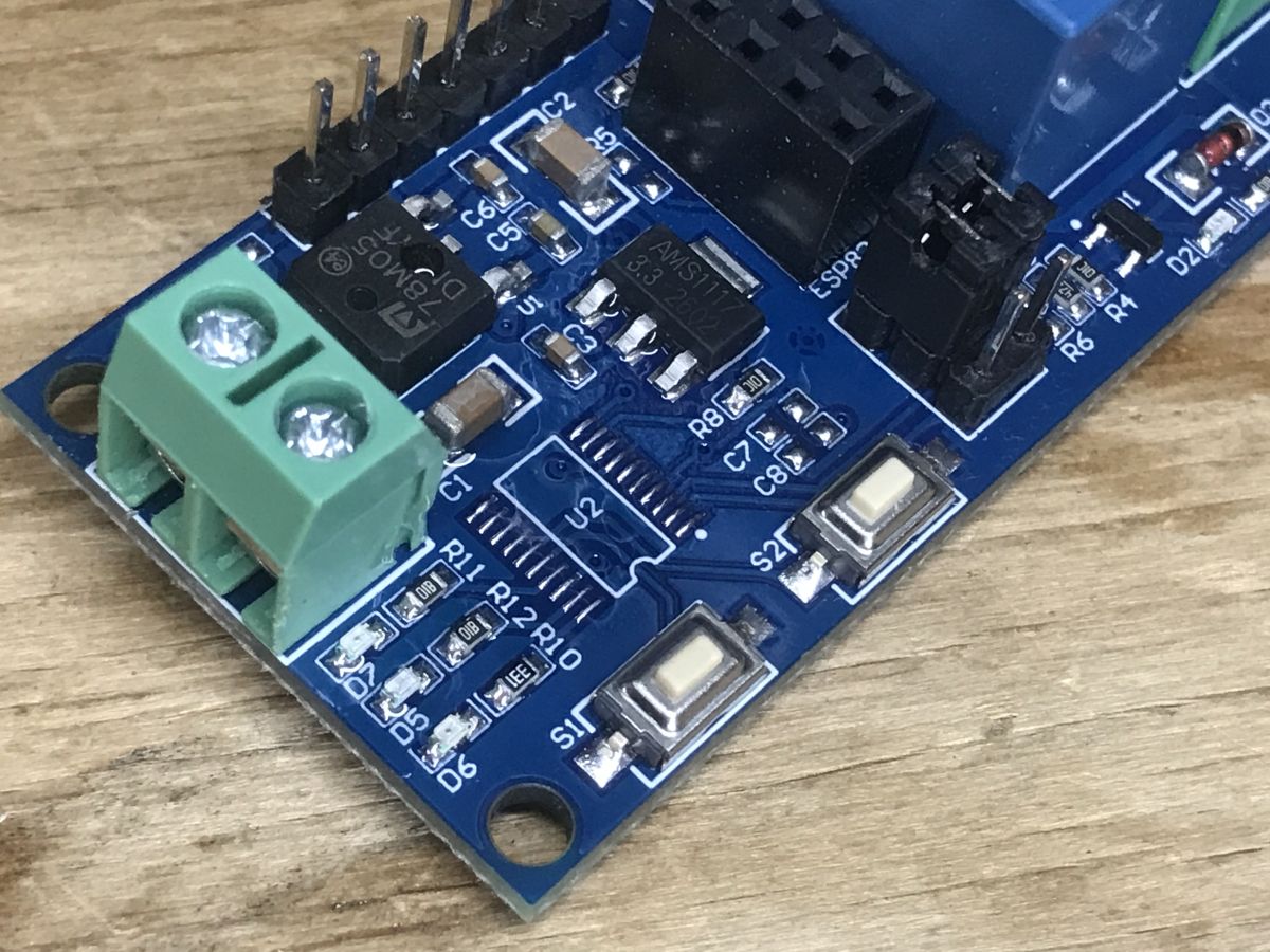
    We are modifying the relay controller so that it works without a microcontroller – ESP8266 Relay V2.
    Next, you need to make the jumpers. The ESP8266-01 only has a 2x4 connector, which carries power, ground, UART and a few GPIO pins, including GPIO0 for programming. You need to be careful with these pins; for example, you mustn’t short GPIO0 to ground during boot-up, as the module will enter flash mode instead of starting up normally.

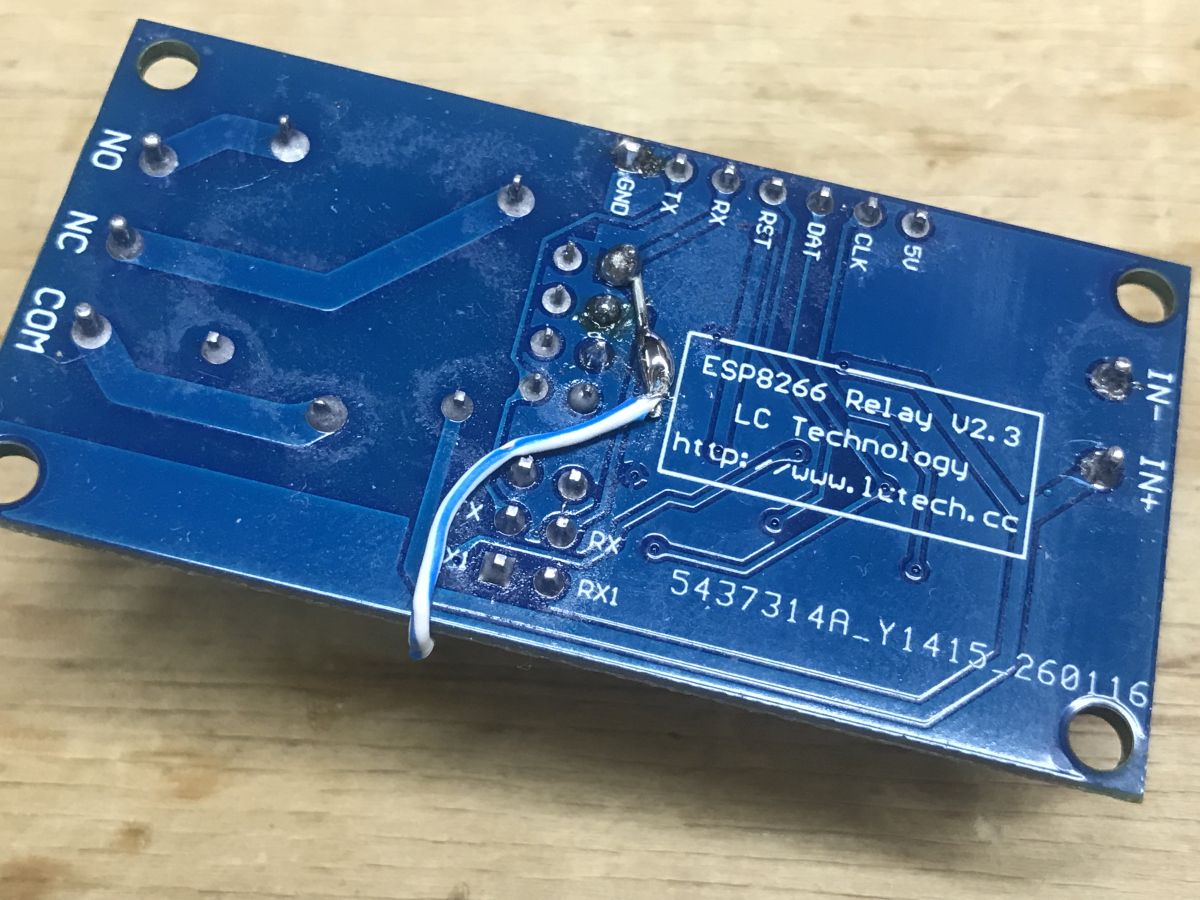
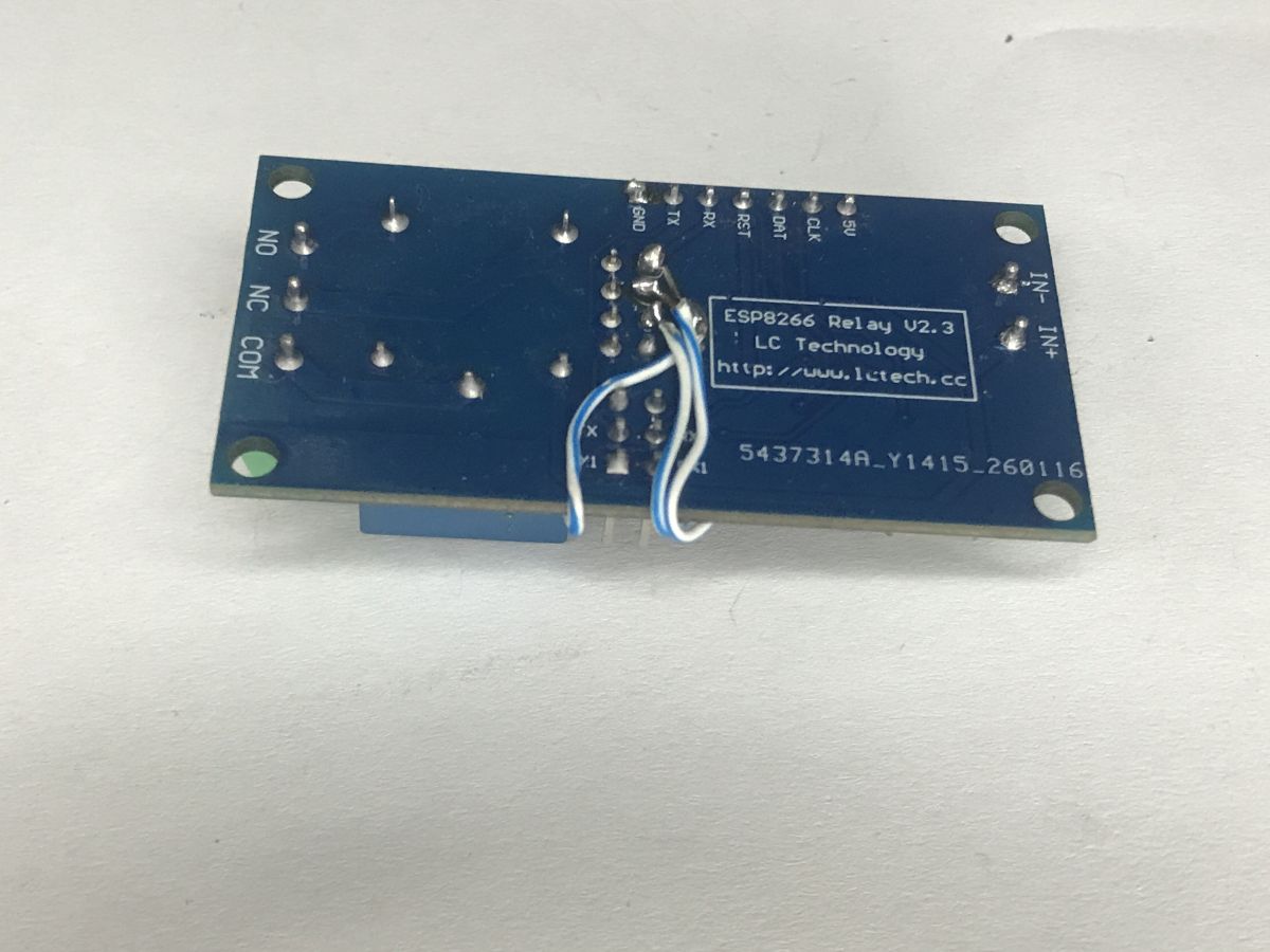
    This is how the relay connection turned out. The entire board requires a 12V DC power supply – this voltage powers the Songle relay coil directly, whilst the board features a 7805 regulator and a separate 3.3V LDO for the ESP8266. The ESP itself, with its 3.3V logic, cannot control the coil directly; therefore, I routed the control signal from the ESP pin via a single wire stripped from an Ethernet cable on the underside of the board to the base resistor R5 (4.7 kΩ, marked 472). This resistor limits the current from the ESP pin and drives transistor Q1 into saturation, connecting the relay coil to earth. Diode D3 is connected in parallel with the coil to suppress voltage spikes when the coil is switched off.
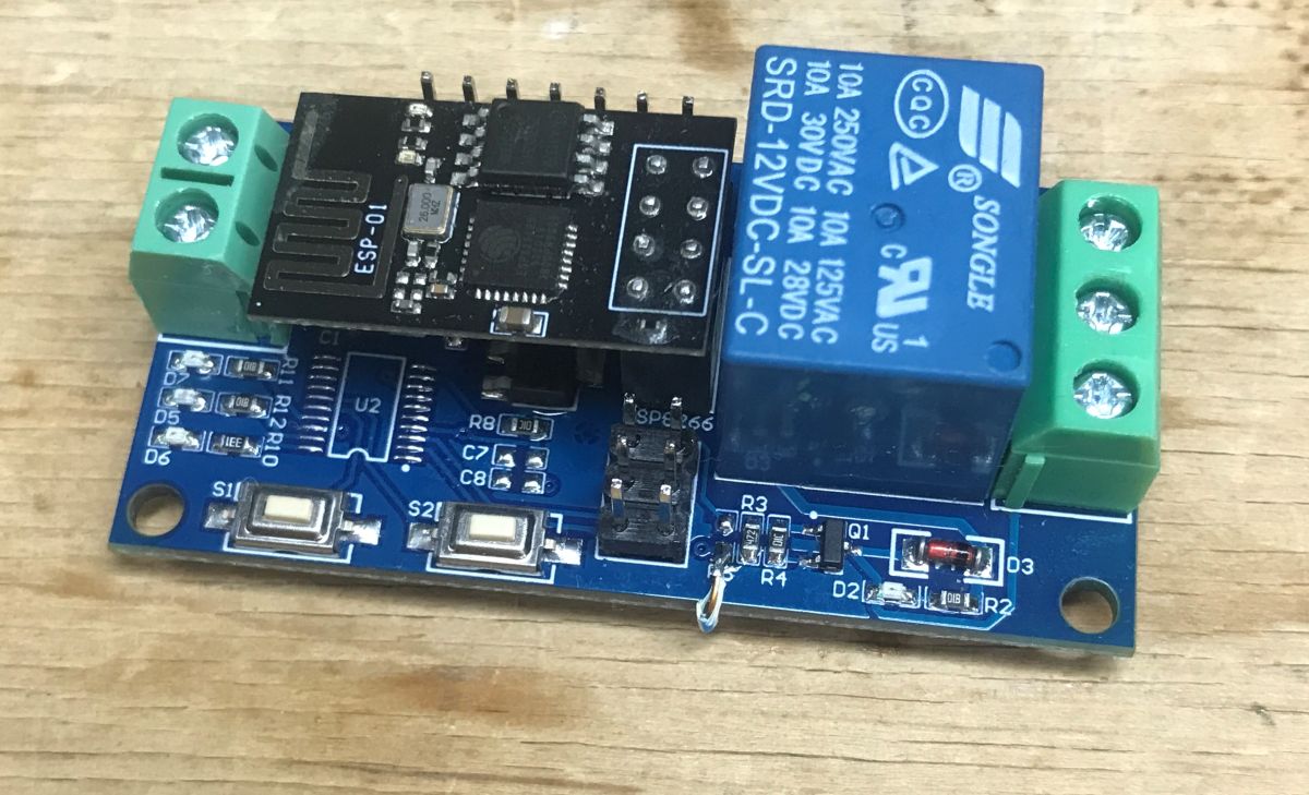
    We are modifying the relay controller so that it works without a microcontroller – ESP8266 Relay V2. We are modifying the relay controller so that it works without a microcontroller – ESP8266 Relay V2.
    I disconnected the button and LED in a similar way. The button is shorted to ground, so it’s ideal for use with GPIO0, just as is done in IoT devices, so that pressing it when power is applied activates programming mode.
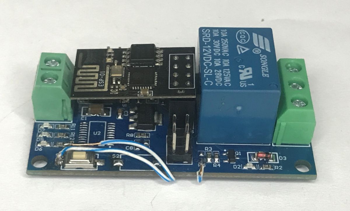
    We are modifying the relay controller so that it works without a microcontroller – ESP8266 Relay V2. We are modifying the relay controller so that it works without a microcontroller – ESP8266 Relay V2.
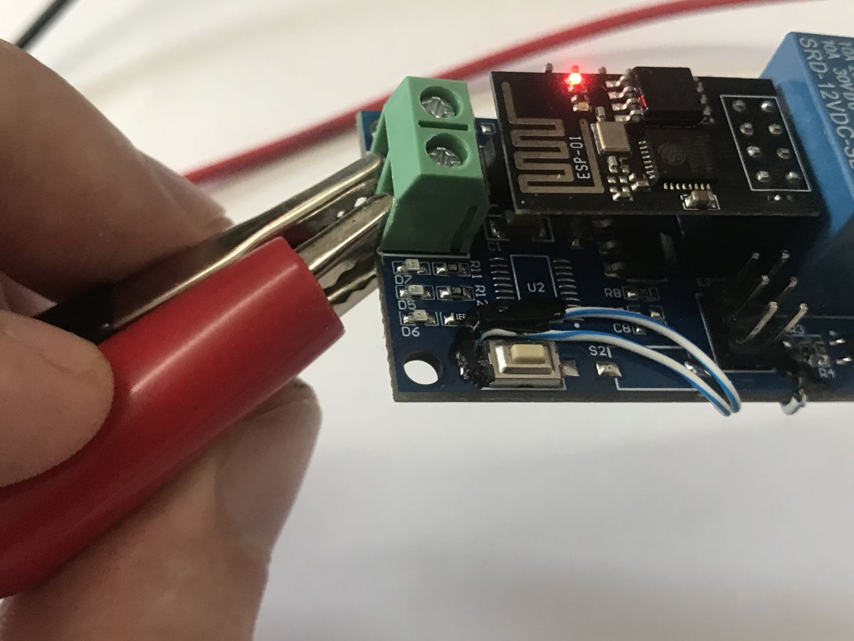
    Finally, I protected the more sensitive areas with a UV-curable solder mask:
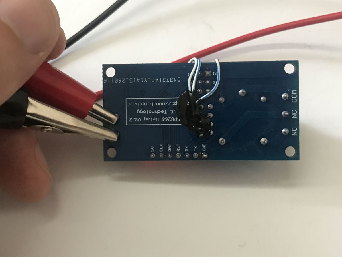
    We are modifying the relay controller so that it works without a microcontroller – ESP8266 Relay V2. We are modifying the relay controller so that it works without a microcontroller – ESP8266 Relay V2.
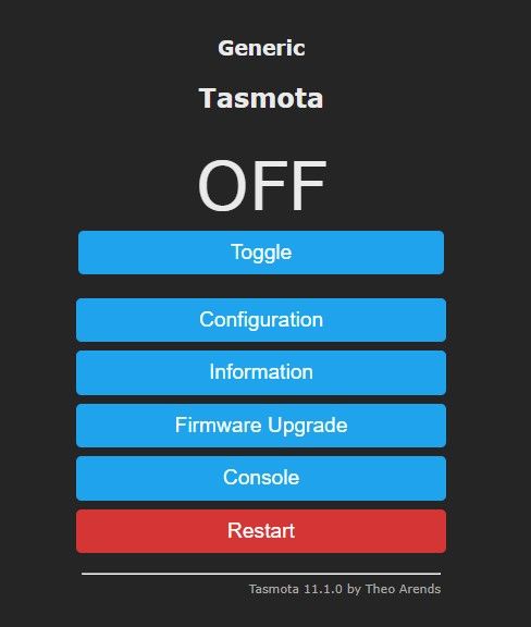
    Final test – the relay control works, both from the Tasmota panel and via the button. Tasmota also detects state changes triggered by the button:


    Settings:
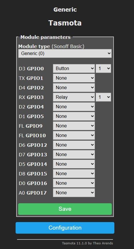
    We are modifying the relay controller so that it works without a microcontroller – ESP8266 Relay V2. We are modifying the relay controller so that it works without a microcontroller – ESP8266 Relay V2.

    To summarise, this was a modification of the relay module to enable it to work with the open-source Tasmota software. It would have been possible to do this without soldering, by sending UART packets via the software so that the microcontroller would interpret them correctly and carry out the commanded operations, but I decided that this made no sense, as I already had the equipment and was keen to do some soldering. We’ve potentially lost one of the two buttons as a result of this modification, as I didn’t connect it to a GPIO pin, but I can’t see any use for it anyway and don’t consider it a loss, especially since… on the Blakadder website, the Tasmota script doesn’t even support reading the relay status from the MCU, so it would have been useless anyway – what’s the point of a button that won’t provide feedback to the Home Assistant interface? For this reason, I consider the modification a success, although I still don’t really know why the MCU is there in the first place – perhaps it’s a remnant from the 2- and 4-channel versions, where pins start to run out completely when using the ESP8266-01? But then again – nobody said you have to use the ESP8266-01; you could use the TYWE3S or similar modules, which have more GPIO pins exposed. Interesting.

    Cool? Ranking DIY
    Helpful post? Buy me a coffee.

    About Author
    p.kaczmarek2
    Moderator Smart Home
    Offline 
    p.kaczmarek2 wrote 14803 posts with rating 12965, helped 659 times. Been with us since 2014 year.
  • ADVERTISEMENT
  • #2 21949483
    austin007
    Level 17  
    Posts: 768
    Help: 6
    Rate: 278
    The title, which reads: “We’re modifying the relay controller so that it works without a microcontroller”, is downright misleading. This doesn’t look good, especially coming from someone with such a self-congratulatory byline. Even after the modification, the device still requires a microcontroller to operate.
    We are modifying the relay controller so that it works without a microcontroller – ESP8266 Relay V2.
    .
  • ADVERTISEMENT
  • Clarifying removal of the additional microcontroller

    #3 21949493
    p.kaczmarek2
    Moderator Smart Home
    Posts: 14803
    Help: 659
    Rate: 12965
    I think you’ll find the explanation for this in the second sentence of the first paragraph, which appears both in the main body of the thread and in the thread preview:
    p.kaczmarek2 wrote:

    This will be quite an unusual modification, because, for some inexplicable reason, the manufacturer decided to use an additional microcontroller to control the relay.

    Your interpretation sounds a bit as though you were expecting the guide to be based on getting rid of the ESP itself – though I wonder how it would work then and still connect to Wi-Fi. Nevertheless, I can add the word ‘additional’ to the title for you.
    Helpful post? Buy me a coffee.
  • Adding additional to clarify the relay controller title

    #4 21949538
    gulson
    System Administrator
    Posts: 29573
    Help: 150
    Rate: 6144
    austin007 wrote:
    is actually rather misleading.

    You’re right, it was a bit confusing without reading the body of the text, but we have a character limit for the title and we still need to include the full board name and the board symbol for cataloguing. The word ‘additional’ is quite long.
    Thanks for pointing that out.

    p.kaczmarek2 wrote:
    Nevertheless, I can add the word ‘additional’ to the title for you.

    Good idea, and a way round the character limit – thank you.
  • ADVERTISEMENT
  • MCU may support expansion or external relay control

    #5 21949551
    madamsz1
    Level 42  
    Posts: 5906
    Help: 1061
    Rate: 1720
    p.kaczmarek2 wrote:
    For this reason, I consider the modification a success, although I still don’t know why the MCU is there in the first place – perhaps it’s some sort of remnant from the 2- and 4-channel versions

    Or perhaps it’s possible to connect a few modules that don’t have an ESP and thus control additional boards or relays.
    Perhaps the relay can be controlled externally, with the ESP merely displaying the relay’s operating status.
  • ADVERTISEMENT
  • Modification succeeds despite unexplained auxiliary MCU

    #6 21949554
    p.kaczmarek2
    Moderator Smart Home
    Posts: 14803
    Help: 659
    Rate: 12965
    This ‘microcontroller’ business is actually becoming a bit of a misnomer in the IoT world, but it’s a popular term, almost like ‘LED bulb’. In the general IoT section, I regularly see questions like “is this an MCU device?”, which is a shorthand for “an IoT device with an additional MCU”. The point is that IoT devices are either based solely on a Wi-Fi module, or feature this very additional MCU; this is often seen in TuyaMCU devices, which have been described here:
    The TuyaMCU protocol – communication between the microcontroller and the Wi-Fi module
    Guide to flashing, installing and configuring TuyaMCU – configure the dpID for Home Assistant
    Apart from that, I frequently see the use of an additional MCU in dimmers, where zero-crossing detection is required to control a triac. I haven’t come across the ESP itself (or Beken, or any other Wi-Fi chip) handling this. It’s interesting why that is, actually; I reckon I could have achieved this on the ESP alone.

    It all makes you wonder a bit – what on earth has happened that we’ve reached a point where a dimmer switch for a lamp in a room has not one, but two microcontrollers, including one with Wi-Fi and Bluetooth...
    Well – what am I saying? Here’s the thread:
    WXDM2 dual dimmer – reverse engineering – strange UART protocol
    so the dimmer contained three microcontrollers (one Wi-Fi module and one MCU per dimmer channel).

    Although I realise this is a bit off-topic, especially as this thread was started for a reader who sent the device all the way from Slovenia so that I could check it and show how it could be adapted for Tasmota.


    madamsz1 wrote:
    p.kaczmarek2 wrote:
    For this reason, I consider the modification a success, although I still don’t really know why this MCU is there in the first place – perhaps it’s a remnant from the 2- and 4-channel versions

    Or perhaps it’s possible to connect a few modules that don’t have an ESP and thus control additional boards or relays.
    Perhaps the relay can be controlled externally, with the ESP merely displaying the relay’s operating status.

    In this specific case, I haven’t heard of that, but generally speaking, expanding on the topic of control via an additional microcontroller, for example, these switches contain the aforementioned TuyaMCU:
    We are modifying the relay controller so that it works without a microcontroller – ESP8266 Relay V2.
    It normally contains this additional microcontroller, and a separate Wi-Fi module; the Wi-Fi module communicates with the microcontroller via UART. In such a situation, this makes sense.

    And here’s another interesting point – in the context of thermostats, also from Tuya:
    We are modifying the relay controller so that it works without a microcontroller – ESP8266 Relay V2.
    They come in three versions:
    - Wi-Fi communication
    - Zigbee communication
    - no communication
    They all contain a microcontroller for control, and those with communication have a separate Wi-Fi or Zigbee module. One of our readers tested this, and his experiments suggest that you can buy the version without communication and add a Wi-Fi module; the MCU inside comes pre-loaded with the TuyaMCU firmware from the factory.... In other words, the factory solder one MCU with one firmware image onto a single PCB, and then equips them with a communication module (or not).
    Helpful post? Buy me a coffee.
  • ESP8266 flashing wiring with GPIO0 and USB-UART converter

    #7 21952084
    p.kaczmarek2
    Moderator Smart Home
    Posts: 14803
    Help: 659
    Rate: 12965
    I forgot to add this to the main thread – photos of the flashing process. GPIO0 is shorted to ground with an extra wire, and a USB-to-UART converter is connected. The 5V from the USB goes to the 5V on the module, which has an AMS1117-3.3V on board.
    We are modifying the relay controller so that it works without a microcontroller – ESP8266 Relay V2. We are modifying the relay controller so that it works without a microcontroller – ESP8266 Relay V2. We are modifying the relay controller so that it works without a microcontroller – ESP8266 Relay V2. We are modifying the relay controller so that it works without a microcontroller – ESP8266 Relay V2. We are modifying the relay controller so that it works without a microcontroller – ESP8266 Relay V2.
    Helpful post? Buy me a coffee.
Listen:
ADVERTISEMENT