logo elektroda
logo elektroda
X
logo elektroda

Understanding Apparent Ground or Virtual Ground in Operational Amplifiers

marslod 25826 13
ADVERTISEMENT
Treść została przetłumaczona polish » english Zobacz oryginalną wersję tematu
  • #1 2939506
    marslod
    Level 15  
    What is apparent ground or virtual ground in an operational amplifier ? I was reading about different amplifiers and such terms I came across, what does it mean and when is it called so ?

    THX
  • ADVERTISEMENT
  • Helpful post
    #2 2939722
    Quarz
    Level 43  
    Hello,
    marslod wrote:
    What is apparent ground or virtual ground in an operational amplifier ?
    this is such a point in the circuit of an operational amplifier. the circuit of an operational amplifier operating with negative feedback , whose potential is equal to (assumed to be zero) and is maintained through this feedback, the reference potential (ground), that is, the midpoint of the symmetrical power supply of this operational amplifier, even though there is no galvanic connection (ohmic) to that point.
    A concept in the theory of operational amplifiers important, because it allows one to benefit in the analysis of such amplifiers from the theorem in Theory of Electrical Circuits of equipotential points (of equal potential).

    Greetings
    Greg.
  • #3 2940036
    marslod
    Level 15  
    Thank you for the explanation :) Where in the diagram this point falls, please provide an example drawing

    Marcin
  • Helpful post
    #4 2940080
    Quarz
    Level 43  
    Hello,
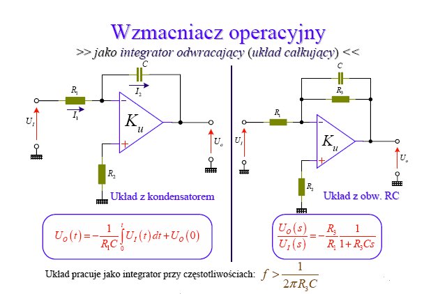
    please, here is a sample schematic:

    Understanding Apparent Ground or Virtual Ground in Operational Amplifiers

    Virtual ground potential on both schematics have inverting (-) inputs of amplifiers.
    And this is mostly the case in all circuits with differential operational amplifiers operating with a closed feedback loop. It is the response of the feedback loop that forces a virtually zero potential difference between the inputs of the amplifier.

    Greetings
    Greg
  • ADVERTISEMENT
  • #6 2977808
    marslod
    Level 15  
    thanks jony nice this course explains a lot :) How to get to the rest of this course, this is the first part and is there the rest ?

    Added after 4 [minutes]:


    And I still have such a question, it is written that a ground potential is forced on the input of the coupling, but I guess not really as I understand only almost ground because there must be a voltage difference between the inputs for the amplifier to work ? The + input is pulled up to ground with a resistor, so it has a ground potential, and the - input from GregB's drawing above has a slightly different voltage than ground ?
  • Helpful post
    #7 2979947
    jony
    Electronics specialist
    marslod wrote:
    thanks jony nice this course explains a lot :) How to get to the rest of this course, this is the first part and is there the rest ?
    The rest of the course is available as a book
    http://www.btc.pl/?id_prod=6308

    marslod wrote:
    And I still have this question, it is written that the ground potential is forced at the input of the coupling, but probably not quite as I understand only almost ground because there must be a voltage difference between the inputs for the amplifier to work ? The + input is pulled up to ground with a resistor, which means it has a ground potential, and the input - from the picture GregBa above has a slightly different voltage than ground ?


    With this apparent ground is that an ideal operational amplifier has a voltage gain of infinite magnitude and the operational amplifier strives to have the same voltage at its inputs.
    That is, for the schematic what GregBa gave.
    The non-inverting input is connected to ground. The amplifier „wants” that the inverting input also has the same voltage, that is, 0V, and so controls the output so that this voltage is 0V. That is, we can say that the inverting input has the same voltage as the non-inverting input, so we have, as it were, a virtual ground on the non-inverting input.
    Look at Fig18 and compare with Fig17 from this course, and you will find the answer to your question about the voltage value of this „almost ground”.
  • #8 2992649
    marslod
    Level 15  
    Ok then the matter of the ground is already understood and everything is fine, but I still have a question about the first filter from Gregb's drawing, when we have a filter such as integral and there is a capacitor in the coupling, how then looks the gain of the amplifier ? We do not have a resistor there and how to calculate it ?


    I still have a question about the filters, I have read about the various filter designs and everything is clear, but I have a problem with understanding how to read the phase characteristics and group delay from the graphs ? Is it good if the phase characteristic is curved on the graph or should it be straight ? How to read from it that the phase is shifted and by how much ? And what is the group delay for what we need it for what it tells us ?

    Heh thanks I guess I will finally know what to do with these OPA

    Marcin
  • ADVERTISEMENT
  • Helpful post
    #9 2992874
    jony
    Electronics specialist
    Hello
    When it comes to the first schematic, the formula for gain is the same Ku=R2/R1 only in this circuit instead of R2 we insert a capacitor C.
    As you know, the capacitor for direct current constitutes a gap i.e. we have an open loop and the gain is equal to the gain of the operational amplifier itself.
    As is known, for alternating current, the capacitor represents a passive resistance called reactance Xc=0.16/F*C depending on the frequency (reactance decreases with increasing frequency).
    So we have an amplifier whose gain is Ku=Xc/R1=0.16/F*R1*C
    With increasing frequency, the resistance of capacitor XC decreases. Thus, the gain also decreases. This circuit is called a low-pass filter because it attenuates high frequencies.


    When it comes to filters, read this
    http://www.edw.com.pl/pdf/k01/69_024.pdf
    https://www.elektroda.pl/rtvforum/topic498307.html
    https://www.elektroda.pl/rtvforum/topic430571.html#2187605


    When in doubt, ask.
    Attachments:
  • #10 2998374
    marslod
    Level 15  
    Ok I understand a lot already, but I have a little confusion when it comes to determining the feedback in an amplifier. I read that when 1-KB is between 0 and 1 then we have positive feedback as 1-KB is >1 then negative, and if it is close to 0 then we get a generator. I understand the description, but I don't really see how when I have, for example, the diagram of the first Gregb, how to determine there what type of feedback is negative or positive ? The point is that if it has an OPA gain, for example K= 1000, what should it do B should give an attenuation of e.g. 500 something to be positive gain ? how does it relate to resistance and capacitance if in the coupling is e.g. a resistor or capacitor, how can I determine from its ohms that it gives a positive or negative coupling ? How to check what is the B of the coupling ?

    I second thing is generators, I read a little about the types and about the condition of amplitude and phase. KB=1 I understand (I think), but what's the matter with the phase, what are the elements to meet to give a total phase shift equal to 0 or otherwise ?

    Uff thanks to you Jony for your patience.
  • Helpful post
    #11 3003081
    jony
    Electronics specialist
    The type of feedback in an operational amplifier is distinguished by the schematic diagram.
    When the feedback signal is fed to the inverting input II (fig1) we are dealing with negative feedback (Negative feedback occurs when the phases of the input signal and the feedback signal are opposite)
    And positive when the feedback signal is fed to the non-inverting input NI (fig2).

    When it comes to b = R2/(R1+R2) is the same for both amplifiers.
    And now an abbreviated analysis of how both couplings work.

    Negative coupling seeks to maintain a state of equilibrium.
    Let's assume that our amplifier operates in slow motion.
    I apply to the input U1= –1V.
    This voltage appears at the inverting input II divided by the voltage divider R1,R2. The amplifier will immediately be driven in the direction of positive voltages.
    With an output voltage of Uo=1V, the voltage difference between the non-inverting input NI and inverting input II is Ud=0V, and in this state the amplifier will stop. If the voltage at the output of WO exceeded 1V, there would be a change in the sign of the voltage Ud ( the difference of voltages between the inputs Ud=NI-II) and so for Uo=1.2V and U1=-1V we have Ud=-0.1V, which means that the amplifier sees on its inverting input 0.1V, so the output voltage will be driven back towards 1V. As you can see, the negative feedback seeks to maintain a state of equilibrium.


    And now the positive feedback which increases the gain.

    Let's look at the situation for an input voltage Uwe=0V and answer the question of whether it is possible for the output to maintain a state of equilibrium then, i.e. Ud=0 and Uwy=0V.
    Let's regret that due to some interference a voltage of 1V appears at the output of the amplifier. This causes the voltage resulting from the division of Uwy on the voltage divider to appear at the non-inverting input. This voltage has the same phase as Uwy and is multiplied by a very large value A of the amplifier. If the output voltage deviated from zero in the direction of positive voltages then Uwy continues to rise and will reach the maximum possible value, that is, the WO enters positive saturation, e.g. Ucc=15.
    We can see that the appearance of a non-zero voltage at the output causes the appearance of a voltage of the same phase at the non-inverting input (0.5V ) which will further increase the output voltage and therefore the imbalance condition deepens.
    The output voltage will almost momentarily reach the maximum possible value, that is, the supply voltage Ucc=15V which means that the voltage at the NI input will be 7.5V.
    Changing the voltage at the input II in the range of Uee to 7.5V does not change anything in the circuit
    Only when the voltage at the input II exceeds 7.5V the circuit will momentarily change state and Uee=-15V will appear at the output. And why will this happen only when 7.5V is applied to the input ??
    I'm curious if you know why this will happen ?

    When it comes to the generator, see here https://www.elektroda.pl/rtvforum/topic385971.html#1954340

    We have there an inverting amplifier with a gain KU=-(R1+R6)/R2=49V/V and a system of three high-pass filters connected in cascade.

    For the system to become a generator we must meet two conditions.
    1. amplitude condition, which requires that the gain of the amplifier times „loop gain” is 1, so that the input and output of the amplifier is the same signal.
    2. phase condition, which says that the phase has to be equal to 0 or n*360 where n=±1,±2...

    Which translates to peasant words. The reason is that on both sides of the amplifier we are supposed to have a voltage of identical amplitude (amplitude condition) and phase (when the voltage at the output increases, the voltage at the input should also increase)

    As we know, an inverting amplifier reverses the phase by 180 degrees, so the task of this RC filter is to shift the phase by another 180 degrees. And what is important, this filter shifts the voltage by 180 degrees only for one specific frequency. That is, we have the phase condition fulfilled.
    Because the attenuation introduced by the RC filter is 1/29
    in this circuit, and to generate oscillations the whole circuit must have a gain greater than 1 so
    the operational amplifier has additional elements added that provide
    local gain slightly greater than 29. attenuation value (often labeled β)
    and the gains multiply - the whole thing has a gain > 1 and then it happily oscillates.
    These diodes are for amplitude stabilization and when the amplitude reaches 1V they reduce the gain of the amplifier to 29V/V.

    Uff a little bit of this.
  • #12 3008537
    marslod
    Level 15  
    O thanks to you for such a comprehensive explanation, you can immediately know a lecturer at the Polytechnic :)

    To your question I will answer yes that this diagram in Figure 2 is impractical because it will snap between one state and another. Here we do not have an argument what compensates only what adds, and now I understand it so that the divider will fix at the state when the amplifier reaches the maximum at the output of 15 V will fix 7.5 V at the input + amplifier. And now when the voltage on the - is below 7.5 volts the + will be greater than the - of the amplifier and the amplifier will amplify the positive voltage and what it amplifies will return again to the input and it will add and it will raise again at the output but the difference in differential voltages is so large that it will saturate quickly and we have 15 volts at the output. If we give a higher voltage to the - than 7.5 V then the - will have a higher voltage than the + and the amplifier will quickly change to a negative voltage at the output, tuning the inputs, and it is enough that we slightly exceed 7.5 V on the input of the - and the differential voltage will quickly be increased by the amplifier and the differential will be large so that it will saturate again - it will be - 15 V.

    I hope that I did not screw something up. Such a circuit is probably practically impractical and not used ?

    I will now read for myself about generators :)

    Thanks to you Jony once again !
  • ADVERTISEMENT
  • #14 3012003
    marslod
    Level 15  
    Well, yes for such an application it is suitable, but I meant that in this configuration then it does not work as analog as filters or generators only almost binary there is a high state or not.

Topic summary

Apparent ground or virtual ground in operational amplifiers refers to a point in the circuit where the potential is maintained at zero volts through negative feedback, despite no direct electrical connection to a true ground. This concept is crucial for analyzing operational amplifiers, particularly in configurations with differential inputs. The inverting input of an operational amplifier typically serves as the virtual ground, where the feedback loop ensures that the voltage difference between the inverting and non-inverting inputs remains negligible. Various circuit configurations, such as low-pass filters, utilize this principle, affecting gain calculations based on the presence of resistors and capacitors. Understanding feedback types—negative and positive—is also essential, as it influences the amplifier's behavior in different applications, including comparators and filters.
Summary generated by the language model.
ADVERTISEMENT