As in the title - today, when integrated circuits have made themselves at home in all sorts of amateur electronic constructions - there is a problem with this. However, is it really?
Of course, I'm not talking about programmable circuits or specialised ICs designed for a specific application - I'll deal with those containing virtually complete amplifier circuit(s), which have earned a well-deserved place at the forefront of audio technology.
The principle is simple: instead of building "on foot" a preamplifier or an equalizer stage using transistors, resistors, capacitors, many of these components can be replaced by one small IC that already contains the "heart" for the whole. And for a specific application, it requires only a few additional components. At the same time, the quality of a preamplifier made in this way, for example, can surpass even systems from the "previous" (solid-state) era, plus it takes up less space!
So much for the (greatly simplified!) introduction.
Advantages abound, but for the amateur electronics technician, sometimes such an operational amplifier is something that one does not really know how it works and there is no (especially) way to verify it.
Of course - you can take measurements with a meter, check the resistances on individual pins, comparing them with a working (brand new) circuit of the same type, but... but not everything can be explored in this way.
So it would be advisable to approach the issue in a different way - to simulate a circuit typical of an operational amplifier and only then verify whether (and how!) it works.
The problem is, however, that no one would likely want to make such a circuit, and moreover, measuring alone takes some time, and still does not always give us 100% certainty - especially if we do not have access to, for example, an oscilloscope. So is it possible to do things differently, more simply?
It turns out that yes. It may not be possible to check the exact catalogue parameters in this way, but within seconds(!) we can verify whether the circuit is working at all. In most cases, this is sufficient. After all, we do not need to check whether the manufacturer's parameters are within a certain tolerance - it is enough to select a dedicated circuit for a specific application. And the catalogue parameters? Let's trust that the manufacturer knows what it's doing....
So how can we test such circuits for potential failure?
As I wrote - it's enough to build a test one, provide it with a socket (8- or 14-legged socket) and power it all somehow.
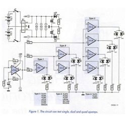
Since the majority of circuits have a typical pinout system, we do not need to build an individual 'tester' for each. One, or rather three, will suffice - for single, double and quadruple circuits (i.e. those containing one, two or four amplifiers independent of the power supply in the structure).
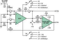
As for the electronic construction itself - it is enough to build an appropriate number (one, two or four) of secondary amplifiers (buffers) and to feed their inputs with the signal from the generator.
And the signal for these amplifiers from where? For example, from a specialised 555 chip, on which we can easily build a SYMETRIC rectangular waveform generator with a relatively low frequency. A small one, so that we can "visually" see on the LED circuits connected to the outputs the waveform after "passing" through the amplifiers.
And how do we check that the circuit is working properly?
Simple: since we are feeding a symmetrical and rectangular signal, this is what we can expect at the WO (operational amplifier) outputs. Of course, the circuit itself should be supplied either with a symmetrical voltage (from two separate power supplies giving symmetrical voltage at the outputs, but with opposite polarity to each other), or create a so-called artificial ground from a single voltage.
Both methods are equally good, although in some respects a symmetrical supply will be preferable. For our needs, however, a single one will suffice. And once upon a time (quite a few years ago), I built such a circuit - out of necessity, because I had quite an elaborate device to make, and because I had about a hundred operational amplifiers "FROM RECOVERY", I decided to use them as much as possible. The circuit works, admittedly, to this day, but - as it turns out - I wasn't the only one to come up with such an idea and very similar testers are on offer on AliExpress.
The description itself may sound like black magic to electronics beginners, but in fact there is a very simple way out of this situation - purchase a 'ready-made' one on AliExpress precisely, where you will find an offer of such circuits from the place you can use them. All you need to do is supply voltage from a stabilised power supply (12V) and plug the circuit under test into the socket. Then it's straightforward - check how the LEDs connected to the outputs blink and, based on this observation, determine whether the circuit is good or not.
And how should these LEDs flash? You have to answer this question yourself - the key is the SYMETRIC input signal. Of course, this is in an ideal situation - in practice, the performance of the test LEDs is affected by the parameters of the circuit under test itself. However - as I can confirm after having done a dozen or so test circuits that worked and those that I was sure were faulty - practice makes perfect. So, after a short time, we will be able to determine not only the efficiency, but also (in the case of abnormalities) in what way the tested circuit is damaged. After all - as I pointed out at the outset - the WO contains a practically complete amplifier structure inside.
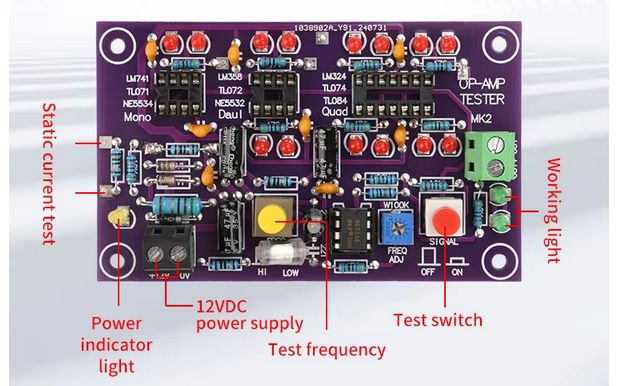
So much theory (deliberately simplified to the necessary minimum). In practice, the testers look like this:
.
.
And closer:
.
Both models work similarly. Both can check single, double and quadruple amplifiers. Both signal operation with LEDs connected to the outputs. And finally, both testers allow the widest variety of circuits to be tested quickly and reliably - provided they have typically spaced-out leads.
And what does it look like in practice?
I have prepared three videos: one showing the operation of a dual comparator (a specific type of operational amplifier) and a second and third of a typical dual circuit - a faulty WO and a functioning one:
A functioning comparator:
.
WO damaged:
WO functioning:
.
(There is an error in the description of one of the auctions regarding just the identification of the efficiency of the tested system - most likely due to an incorrect translation of the original text). .
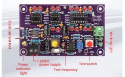
One of the testers (the one shown at the very beginning of the article) is a little more elaborate - it has a separate generator signal switch and generator control, plus the ability to operate in two frequency sub-bands for a more confident circuit check. Personally, I would recommend one for those of you who are (for now) "less involved" in electronics. We can also (this is a suggestion for the advanced) build a similar tester ourselves, according to the descriptions posted in this topic.
Either way, I believe that the testers discussed can find a place among the measuring devices of any electronics technician - especially those specialising in audio.
Regards.
Of course, I'm not talking about programmable circuits or specialised ICs designed for a specific application - I'll deal with those containing virtually complete amplifier circuit(s), which have earned a well-deserved place at the forefront of audio technology.
The principle is simple: instead of building "on foot" a preamplifier or an equalizer stage using transistors, resistors, capacitors, many of these components can be replaced by one small IC that already contains the "heart" for the whole. And for a specific application, it requires only a few additional components. At the same time, the quality of a preamplifier made in this way, for example, can surpass even systems from the "previous" (solid-state) era, plus it takes up less space!
So much for the (greatly simplified!) introduction.
Advantages abound, but for the amateur electronics technician, sometimes such an operational amplifier is something that one does not really know how it works and there is no (especially) way to verify it.
Of course - you can take measurements with a meter, check the resistances on individual pins, comparing them with a working (brand new) circuit of the same type, but... but not everything can be explored in this way.
So it would be advisable to approach the issue in a different way - to simulate a circuit typical of an operational amplifier and only then verify whether (and how!) it works.
The problem is, however, that no one would likely want to make such a circuit, and moreover, measuring alone takes some time, and still does not always give us 100% certainty - especially if we do not have access to, for example, an oscilloscope. So is it possible to do things differently, more simply?
It turns out that yes. It may not be possible to check the exact catalogue parameters in this way, but within seconds(!) we can verify whether the circuit is working at all. In most cases, this is sufficient. After all, we do not need to check whether the manufacturer's parameters are within a certain tolerance - it is enough to select a dedicated circuit for a specific application. And the catalogue parameters? Let's trust that the manufacturer knows what it's doing....
So how can we test such circuits for potential failure?
As I wrote - it's enough to build a test one, provide it with a socket (8- or 14-legged socket) and power it all somehow.
Since the majority of circuits have a typical pinout system, we do not need to build an individual 'tester' for each. One, or rather three, will suffice - for single, double and quadruple circuits (i.e. those containing one, two or four amplifiers independent of the power supply in the structure).
As for the electronic construction itself - it is enough to build an appropriate number (one, two or four) of secondary amplifiers (buffers) and to feed their inputs with the signal from the generator.
And the signal for these amplifiers from where? For example, from a specialised 555 chip, on which we can easily build a SYMETRIC rectangular waveform generator with a relatively low frequency. A small one, so that we can "visually" see on the LED circuits connected to the outputs the waveform after "passing" through the amplifiers.
And how do we check that the circuit is working properly?
Simple: since we are feeding a symmetrical and rectangular signal, this is what we can expect at the WO (operational amplifier) outputs. Of course, the circuit itself should be supplied either with a symmetrical voltage (from two separate power supplies giving symmetrical voltage at the outputs, but with opposite polarity to each other), or create a so-called artificial ground from a single voltage.
Both methods are equally good, although in some respects a symmetrical supply will be preferable. For our needs, however, a single one will suffice. And once upon a time (quite a few years ago), I built such a circuit - out of necessity, because I had quite an elaborate device to make, and because I had about a hundred operational amplifiers "FROM RECOVERY", I decided to use them as much as possible. The circuit works, admittedly, to this day, but - as it turns out - I wasn't the only one to come up with such an idea and very similar testers are on offer on AliExpress.
The description itself may sound like black magic to electronics beginners, but in fact there is a very simple way out of this situation - purchase a 'ready-made' one on AliExpress precisely, where you will find an offer of such circuits from the place you can use them. All you need to do is supply voltage from a stabilised power supply (12V) and plug the circuit under test into the socket. Then it's straightforward - check how the LEDs connected to the outputs blink and, based on this observation, determine whether the circuit is good or not.
And how should these LEDs flash? You have to answer this question yourself - the key is the SYMETRIC input signal. Of course, this is in an ideal situation - in practice, the performance of the test LEDs is affected by the parameters of the circuit under test itself. However - as I can confirm after having done a dozen or so test circuits that worked and those that I was sure were faulty - practice makes perfect. So, after a short time, we will be able to determine not only the efficiency, but also (in the case of abnormalities) in what way the tested circuit is damaged. After all - as I pointed out at the outset - the WO contains a practically complete amplifier structure inside.
So much theory (deliberately simplified to the necessary minimum). In practice, the testers look like this:
.
.
And closer:
.
Both models work similarly. Both can check single, double and quadruple amplifiers. Both signal operation with LEDs connected to the outputs. And finally, both testers allow the widest variety of circuits to be tested quickly and reliably - provided they have typically spaced-out leads.
And what does it look like in practice?
I have prepared three videos: one showing the operation of a dual comparator (a specific type of operational amplifier) and a second and third of a typical dual circuit - a faulty WO and a functioning one:
A functioning comparator:
WO damaged:
WO functioning:
(There is an error in the description of one of the auctions regarding just the identification of the efficiency of the tested system - most likely due to an incorrect translation of the original text). .
One of the testers (the one shown at the very beginning of the article) is a little more elaborate - it has a separate generator signal switch and generator control, plus the ability to operate in two frequency sub-bands for a more confident circuit check. Personally, I would recommend one for those of you who are (for now) "less involved" in electronics. We can also (this is a suggestion for the advanced) build a similar tester ourselves, according to the descriptions posted in this topic.
Either way, I believe that the testers discussed can find a place among the measuring devices of any electronics technician - especially those specialising in audio.
Regards.
Cool? Ranking DIY


